Инструкция по эксплуатации FIAT Bravo
Страница 163
163
СИ
СТ
ЕМ
А
БЕ
ЗО
ПА
СН
ОС
ТИ
СО
ВЕ
ТЫ
ВО
ДИ
ТЕ
ЛЮ
АВ
ТО
МО
БИ
ЛЯ
УС
ТР
АН
ЕН
ИЕ
НЕ
ИС
ПР
АВ
НО
СТ
ЕЙ
ТЕ
ХН
ИЧ
ЕС
КО
Е
ОБ
СЛ
УЖ
ИВ
АН
ИЕ
ТЕ
ХН
ИЧ
ЕС
КИ
Е
ХА
РА
КТ
ЕР
ИС
ТИ
КИ
ПР
ЕД
МЕ
ТН
ЫЙ
УК
АЗ
АТ
ЕЛ
Ь
КО
НТ
РО
ЛЬ
НЫ
Е
ЛА
МП
Ы
И
СО
ОБ
ЩЕ
НИ
Я
ПР
ИБ
ОР
Ы
И О
РГ
АН
Ы
УП
РА
ВЛ
ЕН
ИЯ
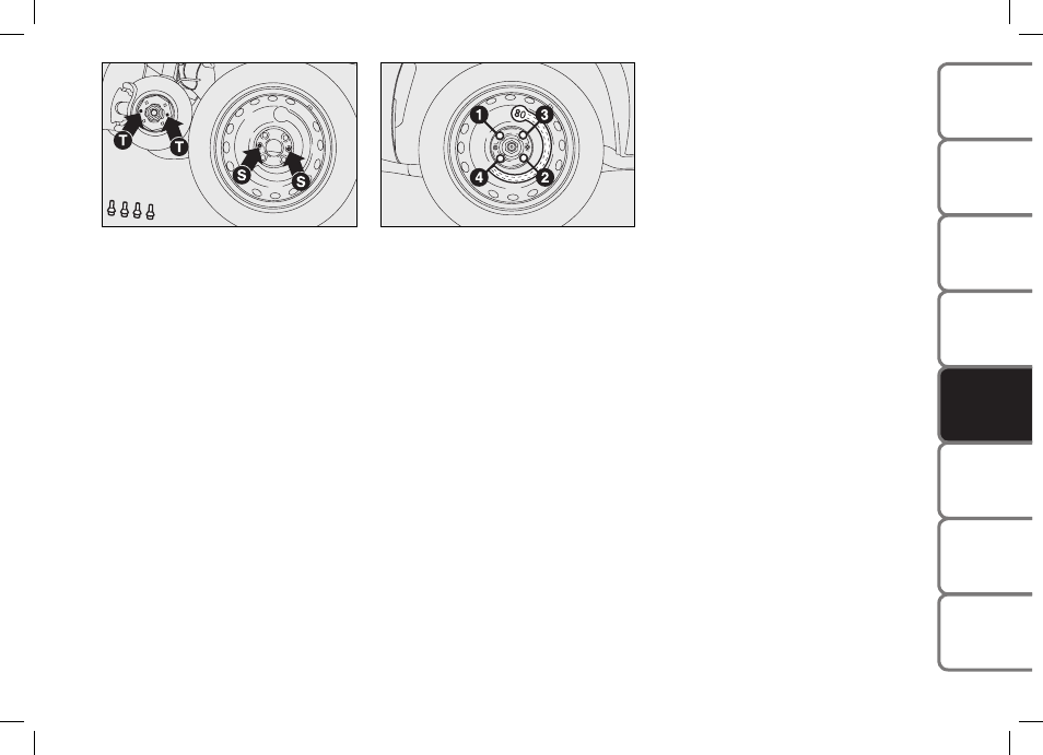
установите запасное колесо-докатку,
совместив отверстия S, рис. 7 с соот-
ветствующими штифтами T;
с помощью гаечного ключа полностью
затяните четыре болта крепления;
используя рукоятку домкрата R, рис.
6
, опустите автомобиль и уберите дом-
крат;
Используя гаечный ключ, затяните
болты крепления колеса в последова-
тельности, указанной на рис. 8.
ЗАМЕНА КОЛЕСА
Выполнив операции, описанные выше,
поднимите автомобиль и снимите запас-
ное колесо.
Модификации со стальными
штампованными дисками
Действуйте следующим образом:
Проверьте, что посадочные поверх-
ности колеса и ступицы чистые, чтобы
крепежные болты не вывернулись;
Установите колесо, совместив отвер-
стия S, рис. 7 с соответствующими
штифтами T;
Затяните болты крепления с помощью
гаечного ключа;
Опустите автомобиль и уберите домк-
рат;
Окончательно затяните болты, исполь-
зуя гаечный ключ, в последователь-
ности, указанной на рис. 8;
Установите на колесо декоративный
колпак так, чтобы вентиль распола-
гался в пазу на крышке;
Нажимайте по окружности декора-
тивного колпака, начиная со сторо-
ны вентиля, пока колпак не будет
полностью установлен.
ВАЖНО: Неправильная установка может
привести к выпадению колпака во вре-
мя движения.
161
SAFETY DEVICES
CORRECT USE OF THE CAR
W
ARNING
LIGHTS AND MESSAGES
CA
R
MA
IN
TE
NA
NC
E
TE
CH
NI
CA
L
SP
EC
IFI
CA
TIO
NS
INDEX
DA
SH
BO
AR
D
AN
D
CO
NT
RO
LS
IN AN
EMERGENCY
❒
install the space-saver spare wheel
matching the holes S-fig. 7 with the
corresponding pins T;
❒
using the wrench provided, fully tight-
en the four fastening bolts;
❒
work the jack handle R-fig.6 to lower
the car and remove the jack;
❒
using the wrench provided, tighten up
the wheel bolts in a criss-cross fashion
following the sequence shown in fig. 8.
REFITTING THE STANDARD
WHEEL
Following the procedure described previ-
ously, raise the car and remove the spare
wheel.
For versions with steel rim
Proceed as follows:
❒
Make sure the contact surfaces be-
tween standard wheel and hub are
clean so that the fastening bolts will not
come loose;
❒
Fit the normal wheel matching the
holes S-fig. 7 with the corresponding
pins T;
❒
Using the wrench provided, tighten the
fastening bolts;
❒
Lower the car and remove the jack;
❒
Using the wrench provided, fully tight-
en the bolts in the sequence shown in
fig. 8;
❒
Place the cap near the wheel so that the
inflation valve can come through the
slot provided on the cap;
❒
Press the circumference of the cap,
starting from the parts nearest the in-
flation valve until it is inserted com-
pletely.
IMPORTANT Incorrect fitting may cause
the wheel cap to come off when the car is
travelling.
fig. 7
F0Q0396m
fig. 8
F0Q0397m
155-190 BRAVO GB 10-05-2007 9:19 Pagina 161
Рис. 7
161
SAFETY DEVICES
CORRECT USE OF THE CAR
W
ARNING
LIGHTS AND MESSAGES
CA
R
MA
IN
TE
NA
NC
E
TE
CH
NI
CA
L
SP
EC
IFI
CA
TIO
NS
INDEX
DA
SH
BO
AR
D
AN
D
CO
NT
RO
LS
IN AN
EMERGENCY
❒
install the space-saver spare wheel
matching the holes S-fig. 7 with the
corresponding pins T;
❒
using the wrench provided, fully tight-
en the four fastening bolts;
❒
work the jack handle R-fig.6 to lower
the car and remove the jack;
❒
using the wrench provided, tighten up
the wheel bolts in a criss-cross fashion
following the sequence shown in fig. 8.
REFITTING THE STANDARD
WHEEL
Following the procedure described previ-
ously, raise the car and remove the spare
wheel.
For versions with steel rim
Proceed as follows:
❒
Make sure the contact surfaces be-
tween standard wheel and hub are
clean so that the fastening bolts will not
come loose;
❒
Fit the normal wheel matching the
holes S-fig. 7 with the corresponding
pins T;
❒
Using the wrench provided, tighten the
fastening bolts;
❒
Lower the car and remove the jack;
❒
Using the wrench provided, fully tight-
en the bolts in the sequence shown in
fig. 8;
❒
Place the cap near the wheel so that the
inflation valve can come through the
slot provided on the cap;
❒
Press the circumference of the cap,
starting from the parts nearest the in-
flation valve until it is inserted com-
pletely.
IMPORTANT Incorrect fitting may cause
the wheel cap to come off when the car is
travelling.
fig. 7
F0Q0396m
fig. 8
F0Q0397m
155-190 BRAVO GB 10-05-2007 9:19 Pagina 161
Рис. 8