Типовая схема соединений, Типовая схема соединений -9, Iem-2020 – Инструкция по эксплуатации Basler Electric IEM-2020
Страница 211
9441073990 Rev B1
Установка IEM-2020
6-9
Типовая схема соединений
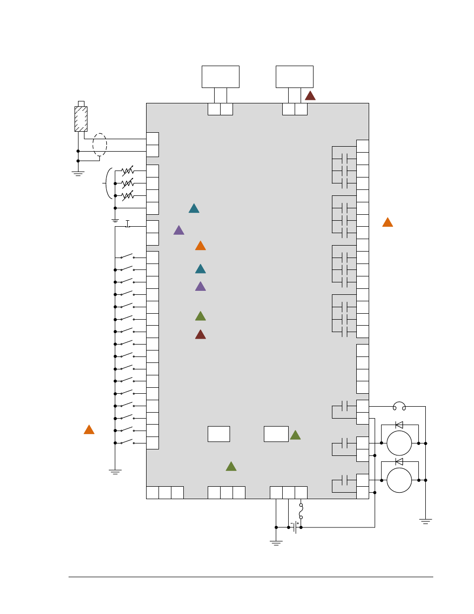
Типовые соединения показаны на рисунке 6-5.
Рисунок 6-7. Соединения при типовом использовании
31
32
MPU+
MPU–
51
52
OUT 1
53
54
55
56
57
58
59
60
61
62
63
64
65
66
OUT 2
OUT 3
OUT 4
OUT 5
OUT 6
OUT 7
OUT 8
OUT 9
OUT 10
OUT 11
OUT 12
PRE
RUN
START
START
SOLENOID
FUEL
SOLENOID
2
BATT
–
3
BATT
+
1
CHASSIS
GLOW PLUGS
8
9
OIL
FUEL
10
11
COOLANT
SENDER COM
46
47
ESTOP
ESTOP
15
16
INPUT 16
17
18
19
20
21
22
23
24
25
26
27
28
29
30
INPUT 15
INPUT 14
INPUT 13
INPUT 12
INPUT 11
INPUT 10
INPUT 8
INPUT 9
INPUT 7
INPUT 6
INPUT 5
INPUT 3
INPUT 4
INPUT 2
INPUT 1
6
RDP BATT–
7
RDP BATT+
Prestart Horn
Speed Up
Speed Down
Warming/Cooling
Emergency
Stop
Pump Run
P
0059
-59
M
P
U
Mechanical
Senders
12/24V
5
RDP TXD–
4
RDP TXD+
Mini-B
USB
Modem
13
485
B
14
485
A
12
485
SHIELD
49
CAN H
50
SHIELD
48
CAN L
1
1
4
4
2
3
IEM-2020
1
Labels indicate the functions assigned by
the default programmable logic to the
contact inputs and output contacts.
2
3
Connect near engine block (negative
battery terminal) side of senders.
4
Jumper terminals 46 and 47 if not using
an emergency stop switch. See
Emergency Stop Input section for
optional wiring methods.
Optional. Refer to style number for
ordering information.
45
AIN V
–
43
AIN V
+
37
AIN I
–
35
AIN I
+
0 – 10 Vdc
Voltage
Transducer
4 – 20 mAdc
Current
Transducer
5
For optimal metering performance, it is
recommended to connect ananlog input
common to BATT
−.
5