Выбор уровней (уровней), Selecting layers – Инструкция по эксплуатации Yamaha dm2000v2e1
Страница 58
DM2000 Version 2—Owner’s Manual
Основы управления микшером
58
Соединения входные, Insert In, Insert Out и Direct Out
Если кодерам заданы параметры Input Patch, Insert In Patch, Insert Out Patch или Direct
Out, дисплеи кодеров показывают ID портов. Информация о соединении с помощью
кодеров приведена на стр. 83.
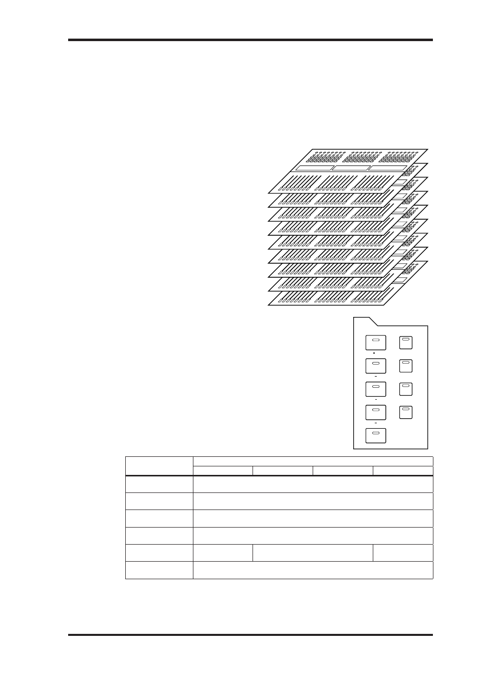
Выбор уровней (уровней)
Входные и выходные каналы упорядочены по 9 уровням: четыре уровня для входных
каналов, один ведущий уровень (или выходной уровень) и четыре удаленных уровня.
Уровень входных каналов 1-24
Уровень входных каналов 25-48
Уровень входных каналов 49-72
Уровень входных каналов 73-96
Ведущий уровень (выходных шин,
дополнительных посылов, посылов Matrix)
Удаленный уровень 1
Удаленный уровень 2
Удаленный уровень 3
Удаленный уровень 4
Для выбора входных и выходных каналов для настройки с по-
мощью регуляторов полос каналов, необходимо выбрать уровень
кнопками LAYER.
Загорится индикатор кнопки LAYER выбранного уровня, а в по-
лосе канала будут отображены короткие имена/идентификаторы
каналов данного уровня.
Выбранный уровень определяет функцию кодеров полос каналов,
кнопок [AUTO], кнопок [SEL], кнопок [SOLO], кнопок [ON], окон
полос каналов и фейдеров. К примеру, если выбран уровень 1-24,
кнопка [SEL] №1 управляет входным каналом №1;, если выбран
уровень 25-48, данная кнопка управляет входным каналом №25, а,
если выбран ведущий уровень – выходной шиной №1.
В таблице показаны входные и выходные каналы, управляемые
полосами каналов в каждом уровне.
Уровни
Полосы канала
1-8
9-16
17-20
21-24
Уровень входных
каналов 1-24
Входные каналы 1-24
Уровень входных
каналов 25-48
Входные каналы 25-48
Уровень входных
каналов 49-72
Входные каналы 49-72
Уровень входных
каналов 73-96
Входные каналы 73-96
Ведущий уровень
Ведущие выход-
ные шины 1-8
Ведущие посылы
Matrix 1-4
Удаленный уровень
1-4
Действие зависит от выбранного назначения сигнала (см. стр. 253).
Функция каждого фейдера полосы канала и кодера также зависит от текущего режима
фейдера (см. стр. 60) и кодера (см. стр. 61) соответственно.
58
Chapter 3—Operating Basics
DM2000 Version 2—Owner’s Manual
Selecting Layers
Input and Output Channels are arranged into Layers, as illustrated below. There are nine
Layers altogether: four Input Channel Layers, one Master Layer (or Output Layer), and four
Remote Layers.
To select Input and Output Channels for editing with the channel
strip controls, you use the LAYER buttons to select a Layer.
The LAYER button indicator for the currently selected Layer lights
up, and the channel strip displays show the Short names/Channel
IDs of the channels on the selected Layer.
The currently selected Layer determines the function of the chan-
nel strip Encoders, [AUTO] buttons, [SEL] buttons, [SOLO] but-
tons, [ON] buttons, channel strip displays, and faders. For
example, when Layer 1–24 is selected, [SEL] button #1 controls
Input Channel #1. When Layer 25–48 is selected, it controls Input
Channel #25. And when the Master Layer is selected, it controls
Bus Out #1.
The following table shows which Input and Output Channels are
controlled by the channel strips for each Layer.
The exact function of each channel strip fader and Encoder also depends on the currently
selected Fader mode and Encoder mode respectively. See “Selecting Fader Modes” on
page 60 and “Selecting Encoder Modes” on page 61 for more information.
Layers
Channel Strips
1–8
9–16
17–20
21–24
1–24
Input Channels 1–24
25–48
Input Channels 25–48
49–72
Input Channels 49–72
73–96
Input Channels 73–96
MASTER
Bus Out masters 1–8
Aux Send masters 1–12
Matrix Send masters 1–4
REMOTE
1–4
Operation depends on the selected target.
See “About Remote Layers” on page 253 for more information.
Input Channels [1–24]
Input Channels [25–48]
Input Channels [49–72]
Input Channels [73–96]
Bus Outs, Aux Sends, Matrix Sends [MASTER]
[REMOTE 1]
[REMOTE 2]
[REMOTE 3]
[REMOTE 4]
8
7
6
5
4
3
2
1
9
10
11
12
13
14
15
16
17
18
19
20
21
22
23
24
8
7
6
5
4
3
2
1
9
10
11
12
13
14
15
16
17
18
19
20
21
22
23
24
8
7
6
5
4
3
2
1
9
10
11
12
13
14
15
16
17
18
19
20
21
22
23
24
8
7
6
5
4
3
2
1
9
10
11
12
13
14
15
16
17
18
19
20
21
22
23
24
8
7
6
5
4
3
2
1
9
10
11
12
13
14
15
16
17
18
19
20
21
22
23
24
8
7
6
5
4
3
2
1
9
10
11
12
13
14
15
16
17
18
19
20
21
22
23
24
8
7
6
5
4
3
2
1
9
10
11
12
13
14
15
16
17
18
19
20
21
22
23
24
8
7
6
5
4
3
2
1
9
10
11
12
13
14
15
16
17
18
19
20
21
22
23
24
8
7
6
5
4
3
2
1
9
10
11
12
13
14
15
16
17
18
19
20
21
22
23
24
REMOTE
1
REMOTE
2
REMOTE
3
REMOTE
4
LAYER
MASTER
1 24
25 48
49 72
73 96