Инструкция по эксплуатации Yamaha dm2000v2e1
Страница 50
DM2000 Version 2—Owner’s Manual
Панель управления и задняя панель
50
Блок элементов питания
50
Chapter 2—Control Surface & Rear Panel
DM2000 Version 2—Owner’s Manual
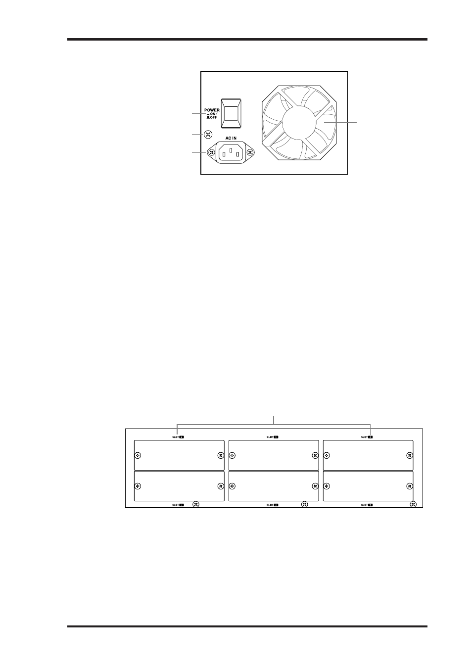
Power Section
A
POWER ON/OFF switch
This switch is used to turn on the power to the DM2000. See “Turning On & Off the
DM2000” on page 51 for more information.
B
Grounding screw
For electrical safety reasons, and correct operation of the touch-sensitive faders, it’s impor-
tant that the DM2000 is grounded properly. The supplied power cord has a three-pin plug,
and if the ground terminal of the AC outlet is grounded, then the unit will be grounded suf-
ficiently through the power cord. If the AC outlet does not provide a suitable ground, this
screw must be connected to a suitable ground point. Grounding is also an effective method
for eliminating hum, interference, and other noise.
C
AC IN connector
This connector is used to connect the DM2000 to an AC outlet via the supplied power cord.
See “Connecting the Power Cord” on page 51 for more information.
D
Cooling fan
The cooling fan expels air out through this outlet. If the airflow is restricted, the DM2000
may overheat, so make sure this outlet is not blocked.
SLOT Section
A
SLOT 1–6
These six slots are for use with optional mini YGDAI cards, which offer a variety of analog
and digital I/O options. See “Slot I/O” on page 70 for more information. Slot inputs can be
patched to Input Channels or Insert Ins. See “Input Patching” on page 77 for more infor-
mation. The following signals can be patched to the Slot Outputs: Bus Outs, Aux Sends,
Matrix Sends, Stereo Out, Insert Outs, Direct Outs, and Surround Monitor Channels. See
“Output Patching” on page 79 for more information.
1
2
4
3
1
Выключатель POWER ON/OFF
Этот выключатель используется для включения питания DM2000. Информация о вклю-
чении и выключении DM2000 приведена на стр. 51.
Болт заземления
Из соображений электробезопасности и правильной работы сенсорных фейдеров важно
должным образом заземлить DM2000. Поставляемый в комплекте кабель имеет 3-х вы-
водной коннектор и, если терминал заземления выхода переменного тока заземлен, то
пульт будет заземлена должным образом через кабель, если выход переменного тока
недостаточно заземлен, этот болт должен быть подсоединен к подходящей точке за-
земления. Заземление также эффективно для избежания приглушения, помех и других
шумов.
Коннектор AC IN
Этот коннектор используется для подключения DM2000 к выходу переменного тока че-
рез поставляемый кабель. Информация о подключении кабеля приведена на стр. 51.
Вентилятор охлаждения
Вентилятор охлаждения прогоняет воздух через отверстие, если поток воздуха затруднен,
DM2000 может перегреться, поэтому убедитесь, что это отверстие ничем не закрыто.
Блок слотов (SLOT)
50
Chapter 2—Control Surface & Rear Panel
DM2000 Version 2—Owner’s Manual
Power Section
A
POWER ON/OFF switch
This switch is used to turn on the power to the DM2000. See “Turning On & Off the
DM2000” on page 51 for more information.
B
Grounding screw
For electrical safety reasons, and correct operation of the touch-sensitive faders, it’s impor-
tant that the DM2000 is grounded properly. The supplied power cord has a three-pin plug,
and if the ground terminal of the AC outlet is grounded, then the unit will be grounded suf-
ficiently through the power cord. If the AC outlet does not provide a suitable ground, this
screw must be connected to a suitable ground point. Grounding is also an effective method
for eliminating hum, interference, and other noise.
C
AC IN connector
This connector is used to connect the DM2000 to an AC outlet via the supplied power cord.
See “Connecting the Power Cord” on page 51 for more information.
D
Cooling fan
The cooling fan expels air out through this outlet. If the airflow is restricted, the DM2000
may overheat, so make sure this outlet is not blocked.
SLOT Section
A
SLOT 1–6
These six slots are for use with optional mini YGDAI cards, which offer a variety of analog
and digital I/O options. See “Slot I/O” on page 70 for more information. Slot inputs can be
patched to Input Channels or Insert Ins. See “Input Patching” on page 77 for more infor-
mation. The following signals can be patched to the Slot Outputs: Bus Outs, Aux Sends,
Matrix Sends, Stereo Out, Insert Outs, Direct Outs, and Surround Monitor Channels. See
“Output Patching” on page 79 for more information.
1
2
4
3
1
SLOT 1–6
Эти шесть слотов используются с дополнительными платами mini YGDAI, предоставляю-
щими широкие возможности аналогового и цифрового ввода/вывода. Информация о
слотах ввода/вывода приведена на стр. 70. Входы слотов могут быть подсоединены в ка-
налы входа или входы Insert In. Информация о соединениях входа приведена на стр. 77.
Следующие сигналы могут быть подсоединены в выходы слотов: Bus Outs, Aux Sends,
Matrix Sends, Stereo Out, Insert Outs, Direct Outs и Surround Monitor Channels. Информа-
ция о соединениях выхода приведена на стр. 79.