Выбор шины aux, Режим кодера, Aux select a – Инструкция по эксплуатации Yamaha dm2000v2e1
Страница 23: Encoder mode, Кнопка aux select display, Кнопки aux 1-12, Кнопка encoder mode display, Кнопка pan, Кнопки aux/mtrx, Control surface
DM2000 Version 2—Owner’s Manual
23
Панель управления и задняя панель
ВЫБОР ШИНЫ AUX
Кнопка AUX SELECT DISPLAY
Выбор следующих страниц: AUX OUTS, PAN AUX OUTS и VIEW IN AUX. Информация о
шинах AUX приведена на стр. 110.
Кнопки AUX 1-12
Используются для выбора шин AUX во время подачи сигнала с канала входа на шины
AUX. При этом загорается индикатор текущей шины AUX, если выбранная шина AUX
спарена, в этом случае мигает индикатор второй шины. Информация о шинах AUX при-
ведена на стр. 110.
Эти кнопки совместно с кнопками включения каналов [ON] включают и выключают
шины AUX (Mix Minus) (стр. 117).
Эти кнопки совместно с кнопками LAYER копируют соответствующий уровень канала в
уровне шины AUX. Они также включают и выключают функции Aux Out Solo при вклю-
ченной связке Aux/Solo (стр. 142).
РЕЖИМ КОДЕРА
Маленькие надписи под кнопкой ASSIGN относятся к удаленному уровню рабочей стан-
ции цифровой обработки звука (DAW). Информация об удаленных уровнях приведена на
стр. 253.
Кнопка ENCODER MODE DISPLAY
Выбор страницы режима кодера. Информация о выборе режима кодера приведена на
стр. 61.
Кнопка PAN
Выбор режима панорамирования кодера. При выборе данного режима загорается соот-
ветствующий индикатор. В этом режиме кодер функционирует как регулятор панорами-
рования, если задан уровень канала входа. При заданном уровне главные кодеры 21-24
функционируют как регуляторы баланса шин матрицы. Остальные кодеры в это время не
активны. Информация о выборе режима кодеров приведена на стр. 61.
Кнопки AUX/MTRX
Выбор режима кодера AUX/MTRX. При выборе данного режима загорается соответ-
ствующий индикатор. В этом режиме кодер функционирует как регулятор шин AUX, если
задан уровень канала входа. При заданном уровне главные кодеры 1-20 функционируют
как регуляторы уровня шин матрицы. Информация о выборе режима кодеров приведена
на стр. 61.
Control Surface
23
DM2000 Version 2—Owner’s Manual
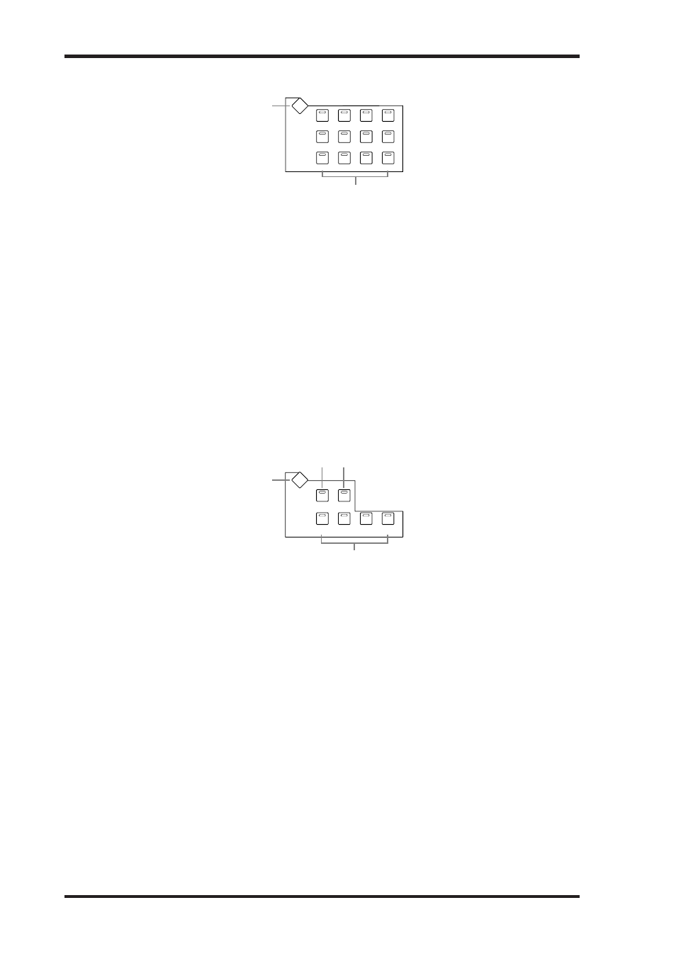
AUX SELECT
A
AUX SELECT DISPLAY button
This button is used to select the following pages: Aux Send, Aux Send Pan, and Input Chan-
nel Aux View. See “Aux Sends” on page 110 for more information.
B
AUX 1–12 buttons
These buttons are used to select Aux Sends when sending Input Channel signals to Aux
Sends. The button indicator of the currently selected Aux Send lights up. If the currently
selected Aux Send is paired, the indicator of its partner flashes. See “Aux Sends” on page 110
for more information.
Using these buttons along with the channel [ON] buttons enables you to turn Aux Sends on
and off (Mix Minus) (page 117).
Using these buttons along with the LAYER buttons enables you to copy the corresponding
channel levels to the Aux Send levels.
These buttons are also used to turn the Aux Out Solo function on and off when Aux/Solo
Link is turned on (page 142).
ENCODER MODE
The small text labels below the ASSIGN buttons apply to the DAW Remote Layer. See
“About Remote Layers” on page 253 for more information.
A
ENCODER MODE DISPLAY button
This button is used to select the Encoder Mode Assign page. See “Selecting Encoder Modes”
on page 61 for more information.
B
PAN button
This button is used to select the Pan Encoder mode. Its indicator lights up when this mode
is selected. In this mode, the Encoders function as Pan controls when an Input Channel
Layer is selected. When the Master Layer is selected, Encoders 21–24 function as Matrix
Send Balance controls. The other Encoders are inactive. See “Selecting Encoder Modes” on
page 61 for more information.
C
AUX/MTRX button
This button is used to select the Aux/Mtrx Encoder mode. Its indicator lights up when this
mode is selected. In this mode, the Encoders function as Aux Send level controls when an
Input Channel Layer is selected. When the Master Layer is selected, Encoders 1–20 function
as Matrix Send level controls. See “Selecting Encoder Modes” on page 61.
AUX
2
AUX
1
AUX
3
AUX
4
AUX
6
AUX
5
AUX
7
AUX
10
AUX
9
AUX
11
AUX
8
AUX
12
AUX SELECT
DISPLAY
1
2
AUX/ MTRX
PAN
ASSIGN
4
ASSIGN
3
DISPLAY
ASSIGN
2
ASSIGN
1
PAN
SEND LEVEL
INSERT
SEND ASSIGN
OUTPUT
INPUT
1
4
2 3
ENCODER MODE
Control Surface
23
DM2000 Version 2—Owner’s Manual
AUX SELECT
A
AUX SELECT DISPLAY button
This button is used to select the following pages: Aux Send, Aux Send Pan, and Input Chan-
nel Aux View. See “Aux Sends” on page 110 for more information.
B
AUX 1–12 buttons
These buttons are used to select Aux Sends when sending Input Channel signals to Aux
Sends. The button indicator of the currently selected Aux Send lights up. If the currently
selected Aux Send is paired, the indicator of its partner flashes. See “Aux Sends” on page 110
for more information.
Using these buttons along with the channel [ON] buttons enables you to turn Aux Sends on
and off (Mix Minus) (page 117).
Using these buttons along with the LAYER buttons enables you to copy the corresponding
channel levels to the Aux Send levels.
These buttons are also used to turn the Aux Out Solo function on and off when Aux/Solo
Link is turned on (page 142).
ENCODER MODE
The small text labels below the ASSIGN buttons apply to the DAW Remote Layer. See
“About Remote Layers” on page 253 for more information.
A
ENCODER MODE DISPLAY button
This button is used to select the Encoder Mode Assign page. See “Selecting Encoder Modes”
on page 61 for more information.
B
PAN button
This button is used to select the Pan Encoder mode. Its indicator lights up when this mode
is selected. In this mode, the Encoders function as Pan controls when an Input Channel
Layer is selected. When the Master Layer is selected, Encoders 21–24 function as Matrix
Send Balance controls. The other Encoders are inactive. See “Selecting Encoder Modes” on
page 61 for more information.
C
AUX/MTRX button
This button is used to select the Aux/Mtrx Encoder mode. Its indicator lights up when this
mode is selected. In this mode, the Encoders function as Aux Send level controls when an
Input Channel Layer is selected. When the Master Layer is selected, Encoders 1–20 function
as Matrix Send level controls. See “Selecting Encoder Modes” on page 61.
AUX
2
AUX
1
AUX
3
AUX
4
AUX
6
AUX
5
AUX
7
AUX
10
AUX
9
AUX
11
AUX
8
AUX
12
AUX SELECT
DISPLAY
1
2
AUX/ MTRX
PAN
ASSIGN
4
ASSIGN
3
DISPLAY
ASSIGN
2
ASSIGN
1
PAN
SEND LEVEL
INSERT
SEND ASSIGN
OUTPUT
INPUT
1
4
2 3
ENCODER MODE