Инструкция по эксплуатации Yamaha dm2000v2e1
Страница 29
DM2000 Version 2—Owner’s Manual
29
Панель управления и задняя панель
Кнопка стерео (STEREO)
Используется для маршрутизации выбранного канала входа на Stereo Outs. Ее индикатор за-
горается при нажатии. Информация о маршрутизации каналов входа приведена на стр. 93.
Кнопка прямой выход (DIRECT)
Используется для маршрутизации выбранного канала входа на его Прямой выход.
Ее индикатор загорается при нажатии. Информация о маршрутизации каналов входа
приведена на стр. 93.
Кнопки Маршрутизация 1-8
Используются для маршрутизации выбранного канала входа на выходных шин Bus. Ин-
дикаторы кнопок шин выхода, на которые направлен канал входа, загораются. Инфор-
мация о маршрутизации каналов входа приведена на стр. 93.
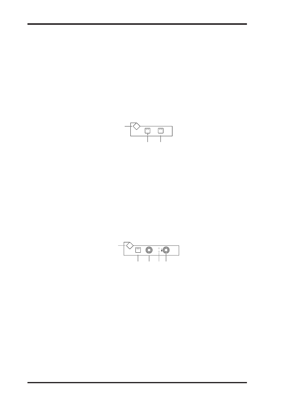
ФАЗА/ВСТАВКА
Кнопка Дисплей фазы/вставки (PHASE/INSERT DISPLAY)
Используется для выбора страниц Фаза канала входа и вставка. Информация об изме-
нении фазы сигнала приведена на стр. 84, об использовании вставок – на стр. 135.
Кнопка фаза (Phase [φ])
Используется для изменения фазы сигнала в выбранном канале входа. Ее индикатор
загорается при изменении фазы. Информация об изменении фазы сигнала приведена
на стр. 84.
Кнопка включение вставки (INSERT ON)
Используется для включения и выключения вставки в выбранном канале. Ее индикатор
загорается при включении вставки. Информация об использовании вставок приведена
на стр. 135.
ЗАДЕРЖКА
Кнопка Окно режимов задержки (DELAY DISPLAY)
Используется для выбора страниц задержки. Информация о задержке сигналов канала
приведена на стр. 141.
Кнопка включение (ON)
Используется для включения и выключения задержки выбранного канала. Ее индика-
тор загорается при включении функции задержки. Информация о задержке сигналов
канала приведена на стр. 141.
Регулятор время (TIME)
Этот регулятор используется для установки времени задержки для функции Задержки
текущего канала. Информация о задержке сигналов канала приведена на стр. 141.
Индикаторы двусторонней связи (FB/MIX)
Эти индикаторы показывают, установлен ли регулятор FB/MIX на регуляцию усиления
двусторонней связи (Feedback Gain) или сведение двусторонней связи (Feedback Mix).
Индикатор FB загорается во время регуляции усиления двусторонней связи, индикатор
MIX - во время регуляции сведения двусторонней связи. Информация о задержке сиг-
налов канала приведена на стр. 141.
Control Surface
29
DM2000 Version 2—Owner’s Manual
E
ROUTING 1–8 buttons
These buttons are used to route the currently selected Input Channel to the Bus Outs. The
button indicators of Bus Outs to which the Input Channel is routed light up. See “Routing
Input Channels” on page 93 for more information.
PHASE/INSERT
A
PHASE/INSERT DISPLAY button
This button is used to select the Input Channel Phase and Insert pages. See “Reversing the
Signal Phase” on page 84 and “Using Inserts” on page 135 for more information.
B
Phase [ ] button
This button is used to reverse the signal phase of the currently selected Input Channel. Its
indicator lights up when the phase is reversed. See “Reversing the Signal Phase” on page 84
for more information.
C
INSERT ON button
This button is used to turn on and off the Insert of the currently selected channel. Its indi-
cator lights up when the Insert is on. See “Using Inserts” on page 135 for more information.
DELAY
A
DELAY DISPLAY button
This button is used to select the Delay pages. See “Delaying Channel Signals” on page 141
for more information.
B
ON button
This button is used to turn on and off the Delay of the currently selected channel. Its indi-
cator lights up when the Delay function is on. See “Delaying Channel Signals” on page 141
for more information.
C
TIME control
This control is used to set the delay time of the currently selected channel’s Delay function.
See “Delaying Channel Signals” on page 141 for more information.
D
FB/MIX indicators
These indicators show whether the FB/MIX control is set to control Feedback Gain or Feed-
back Mix. The FB indicator lights up when it’s set to control Feedback Gain; the MIX indi-
cator, when its set to control Feedback Mix. See “Delaying Channel Signals” on page 141 for
more information.
E
FB/MIX control
This is a rotary control and push switch. When the currently selected channel is an Input
Channel, the push switch can be used to select either Feedback Gain (FB) or Feedback Mix
(MIX). The rotary control is used to set the Feedback Gain or Feedback Mix, as selected by
the push switch. See “Delaying Channel Signals” on page 141 for more information.
PHASE / INSERT
INSERT ON
DISPLAY
1
2
3
DELAY
ON
TIME
FB
MIX
DISPLAY
1
2 3 4 5