Режим фейдера, Выбор информации на дисплее, Fader mode a – Инструкция по эксплуатации Yamaha dm2000v2e1
Страница 24: Display access a
DM2000 Version 2—Owner’s Manual
Панель управления и задняя панель
24
Кнопки ASSIGN 1-4
Выбор возможных режимов кодера. При выборе данного режима загорается соответствую-
щий индикатор. В этом режиме кодер функционирует в зависимости от заданных параме-
тров. Для этих четырех кнопок можно задать до четырех из пятидесяти параметров. Инфор-
мация о задании параметров для кнопок режима кодера ASSIGN приведена на стр. 62.
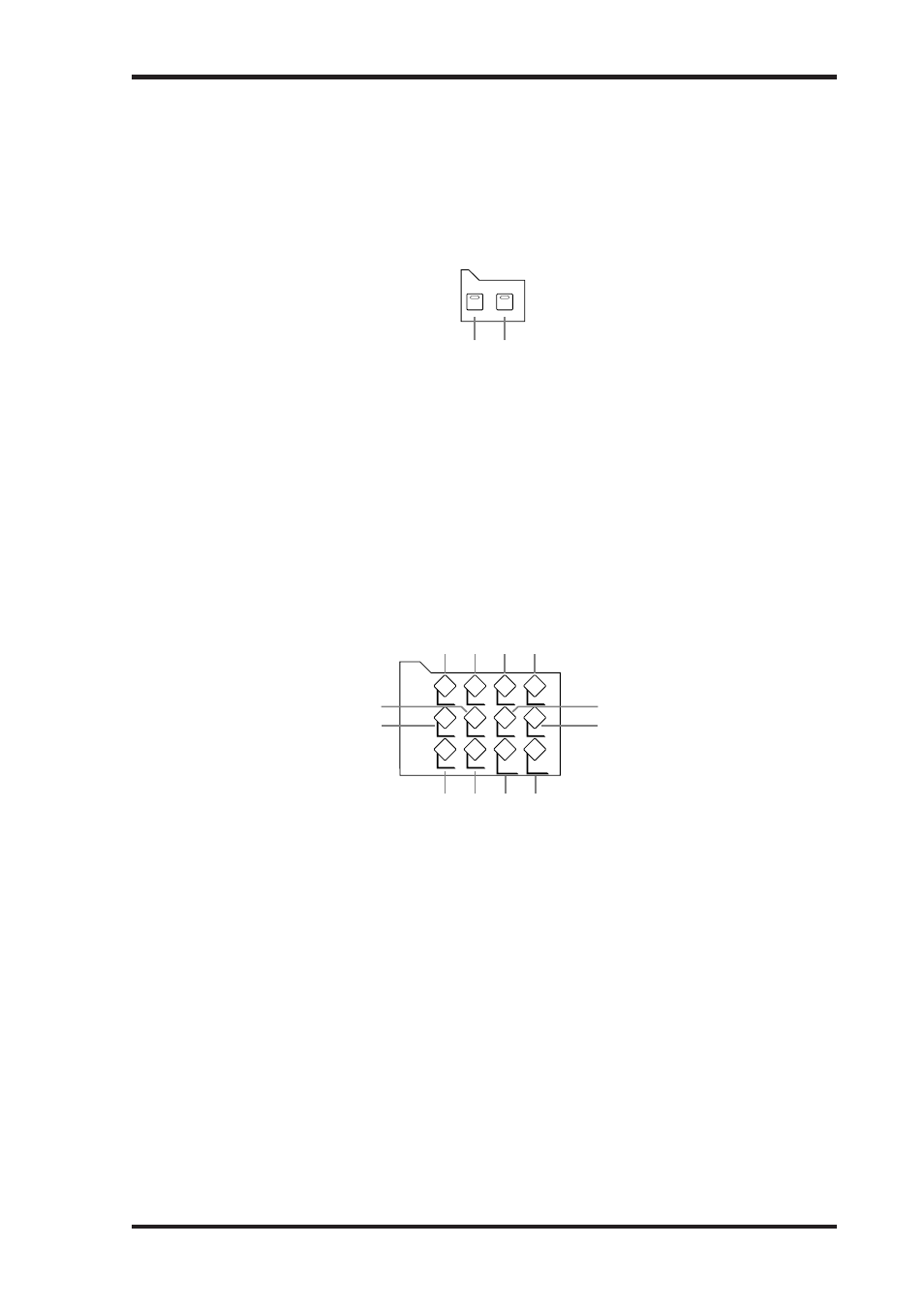
РЕЖИМ ФЕЙДЕРА
Кнопка FADER
Выбор режима FADER, в котором фейдер контролирует уровни каналов входа и выхода в
зависимости от текущего уровня. Информация о выборе режимов FADER приведена на
стр. 60.
Кнопка AUX/MTRX
Эта кнопка предназначена для выбора режима фейдера AUX/MTRX, в котором фейдер
контролирует уровень шины AUX и шины MATRIX в зависимости от текущего уровня. При
выборе данного режима загорается соответствующий индикатор. Информация о выборе
режимов фейдера приведена на стр. 60.
ВЫБОР ИНФОРМАЦИИ НА ДИСПЛЕЕ
Кнопка DATA
Используется для выбора страниц: Save, Load и File, которые используются для сохране-
ния и загрузки данных DM2000 на плату SmartMedia. Информация о сохранении данных
DM2000 на плату SmartMedia приведена на стр. 271.
Кнопка DIO
Используется для следующих страниц: Word Clock Select, Dither, Cascade In, Cascade
Out, Sampling Rate Converter и Higher Sample Rate Data Transfer Format. Информация о
цифровом вводе/выводе и каскадировании приведена на стр. 66.
Кнопка SETUP
Используется для выбора следующих страниц: Select 1, Select 2, Select 3, MIDI/TO
HOST Settings, GPI Settings, Input Port Name, Output Port Name, Time Reference, Time
Signature, Remote Port Setup, Surround Bus.
Кнопка UTILITY
Используется для выбора следующих страниц: Oscillator, Channel Status Monitor, Battery
Check и Operation Lock.
24
Chapter 2—Control Surface & Rear Panel
DM2000 Version 2—Owner’s Manual
D
ASSIGN 1–4 buttons
These buttons are used to select the assignable Encoder modes. The button indicator for the
currently selected mode lights up. When an assignable mode is selected, the function of the
Encoders depends on the assigned parameter. Up to four parameters, from a list of 50, can
be assigned to these four buttons. See “Assigning Parameters to the ENCODER MODE
Assign Buttons” on page 62 for more information.
FADER MODE
A
FADER button
This button selects Fader mode, in which the faders control Input or Output Channel levels,
depending on the currently selected Layer. Its indicator lights up when this mode is selected.
See “Selecting Fader Modes” on page 60 for more information.
B
AUX/MTRX button
This button selects the Aux/Mtrx Fader mode, in which the faders control Aux Send or
Matrix Send levels, depending on the currently selected Layer. Its indicator lights up when
this mode is selected. See “Selecting Fader Modes” on page 60 for more information.
DISPLAY ACCESS
A
DATA button
This button is used to select the Save, Load, and File pages, which are used to save and load
DM2000 data to SmartMedia. See “Saving DM2000 Data to SmartMedia” on page 271 for
more information.
B
DIO button
This button is used to select the following pages: Word Clock Select, Dither, Cascade In,
Cascade Out, Sampling Rate Converter, and Higher Sample Rate Data Transfer Format. See
“Digital I/O & Cascading” on page 66 for more information.
C
SETUP button
This button is used to select the following pages: Preferences 1, Preferences 2, Preferences 3,
MIDI/TO HOST Setup, GPI Setup, Input Port Name, Output Port Name, Time Reference,
Time Signature, Remote Port Setup, and Surround Bus Setup.
D
UTILITY button
This button is used to select the following pages: Oscillator, Channel Status Monitor, Bat-
tery Check, and Operation Lock.
E
REMOTE button
This button is used to select the Remote pages. See “About Remote Layers” on page 253 for
more information.
AUX/ MTRX
FADER
FADER MODE
1 2
DATA
DIO
SETUP
UTILITY
MIDI
REMOTE METER
VIEW
PAIR
GROUP
INPUT
PATCH
OUTPUT
PATCH
9
6
5
8
7
1 2 3 4
J K L
DISPLAY ACCESS