46 блок ац-входа – Инструкция по эксплуатации Yamaha dm2000v2e1
Страница 46
DM2000 Version 2—Owner’s Manual
Панель управления и задняя панель
46
Блок АЦ-входа
46
Chapter 2—Control Surface & Rear Panel
DM2000 Version 2—Owner’s Manual
AD Input Section
A
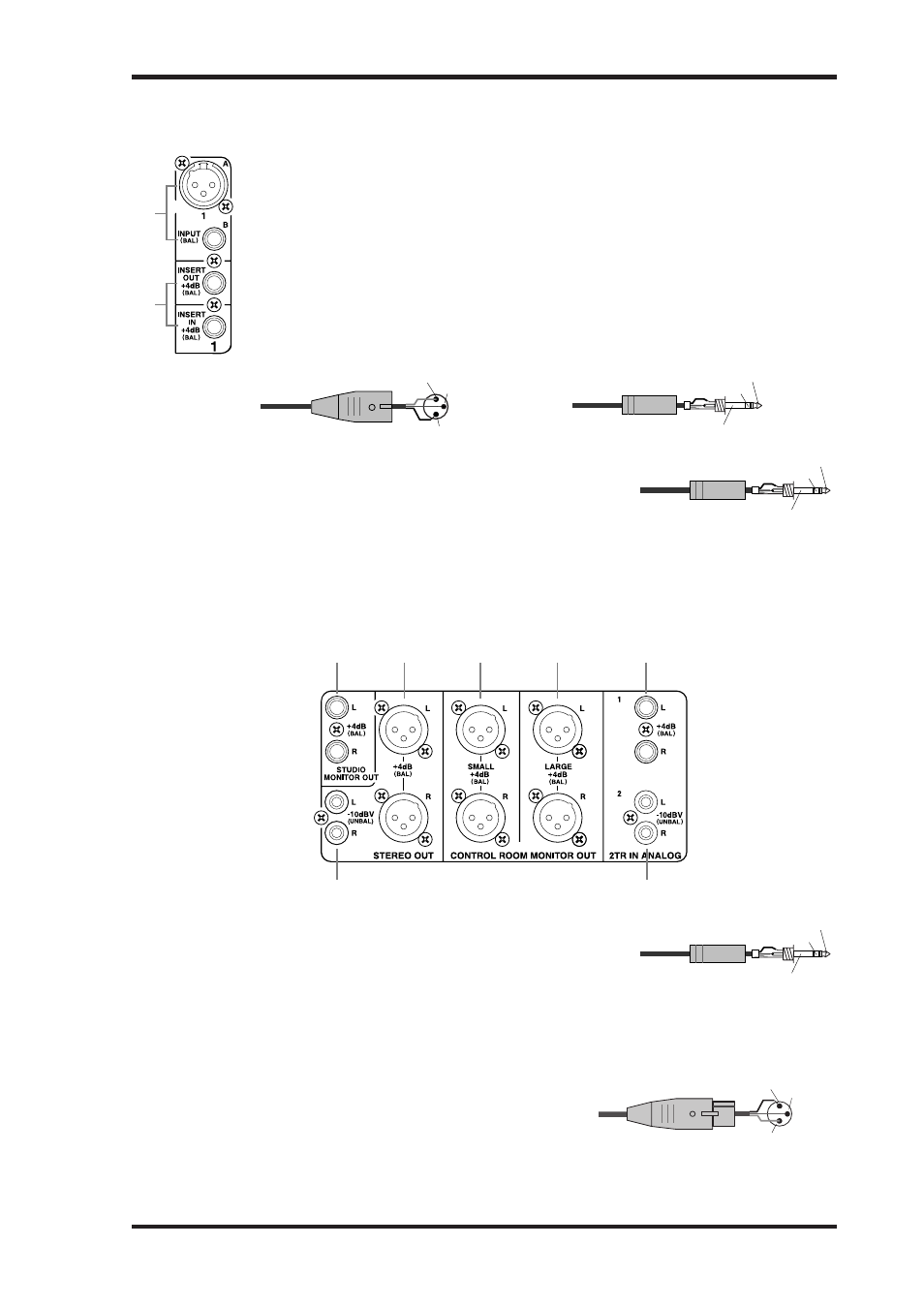
INPUT A & B (BAL) connectors
AD Inputs 1 through 24 feature balanced XLR-3-31-type connectors and bal-
anced 1/4-inch phone jacks, both with a nominal input range of –60 dB to
+10 dB. Phantom powering (+48 V) is supplied to the XLR-type connectors, with
individual ON/OFF switches on each input. The phone jacks, which can also be
used with unbalanced phone plugs, have priority over the XLR-type connectors,
so when a phone plug is inserted, the XLR-type connector is disconnected. These
inputs can be patched individually to the Input Channels or Insert Ins. With their
high sensitivity and PAD switches, these inputs can handle a wide range of signals,
from condenser microphones to “hot” line levels. See “AD Input Section” on page
64 for more information.
B
INSERT IN & OUT +4dB (BAL) connectors
These balanced 1/4-inch TRS phone jacks are used to insert
external signal processors, etc., into AD Inputs 1 through
24. They are wired: sleeve–ground, ring–cold, tip–hot. The
nominal signal level of both jacks is +4 dB. Inserts can be
turned on and off individually by using the INSERT
ON/OFF switches. See “AD Input Section” on page 64 for
more information.
Analog Master I/O Section
A
STUDIO MONITOR OUT +4 dB (BAL)
These balanced 1/4-inch TRS phone jacks, nominal output
level +4 dB, output the analog Studio Monitor signal for
monitoring in the actual studio. The source, which is
selected by using the STUDIO buttons in the MONITOR
section, can be Aux Send #11, Aux Send #12, the Stereo Out, or Control Room. The output
level is controlled by the STUDIO LEVEL control. See “Studio Monitoring” on page 159 for
more information.
2
1
Male XLR plug
1 (ground)
2 (hot)
3 (cold)
1/4" TRS phone plug
Tip (hot)
Ring (cold)
Sleeve (ground)
1/4" TRS phone plug
Tip (hot)
Ring (cold)
Sleeve (ground)
2
1
6
7
5
3
4
1/4" TRS phone plug
Tip (hot)
Ring (cold)
Sleeve (ground)
46
Chapter 2—Control Surface & Rear Panel
DM2000 Version 2—Owner’s Manual
AD Input Section
A
INPUT A & B (BAL) connectors
AD Inputs 1 through 24 feature balanced XLR-3-31-type connectors and bal-
anced 1/4-inch phone jacks, both with a nominal input range of –60 dB to
+10 dB. Phantom powering (+48 V) is supplied to the XLR-type connectors, with
individual ON/OFF switches on each input. The phone jacks, which can also be
used with unbalanced phone plugs, have priority over the XLR-type connectors,
so when a phone plug is inserted, the XLR-type connector is disconnected. These
inputs can be patched individually to the Input Channels or Insert Ins. With their
high sensitivity and PAD switches, these inputs can handle a wide range of signals,
from condenser microphones to “hot” line levels. See “AD Input Section” on page
64 for more information.
B
INSERT IN & OUT +4dB (BAL) connectors
These balanced 1/4-inch TRS phone jacks are used to insert
external signal processors, etc., into AD Inputs 1 through
24. They are wired: sleeve–ground, ring–cold, tip–hot. The
nominal signal level of both jacks is +4 dB. Inserts can be
turned on and off individually by using the INSERT
ON/OFF switches. See “AD Input Section” on page 64 for
more information.
Analog Master I/O Section
A
STUDIO MONITOR OUT +4 dB (BAL)
These balanced 1/4-inch TRS phone jacks, nominal output
level +4 dB, output the analog Studio Monitor signal for
monitoring in the actual studio. The source, which is
selected by using the STUDIO buttons in the MONITOR
section, can be Aux Send #11, Aux Send #12, the Stereo Out, or Control Room. The output
level is controlled by the STUDIO LEVEL control. See “Studio Monitoring” on page 159 for
more information.
2
1
Male XLR plug
1 (ground)
2 (hot)
3 (cold)
1/4" TRS phone plug
Tip (hot)
Ring (cold)
Sleeve (ground)
1/4" TRS phone plug
Tip (hot)
Ring (cold)
Sleeve (ground)
2
1
6
7
5
3
4
1/4" TRS phone plug
Tip (hot)
Ring (cold)
Sleeve (ground)
Коннекторы INPUT A & B (BAL)
АЦ входы с 1 по 24 представляют собой симметричные коннекторы XLR-3-31 и сим-
метричные коннекторы «джек» для наушников ¼ дюйма. Оба типа имеют номиналь-
ный входной диапазон от -60 дБ до +10 дБ. Фантомное питание (+48 В) подведено к
коннекторам XLR с индивидуальными переключателями ON/OFF на каждом входе.
Коннекторы «джек» для наушников, которые также могут использоваться с несим-
метричными штекерами для наушников, имеют преимущество перед коннекторами
XLR, поэтому, когда вставлен штекер наушников, коннекторы XLR отсоединяются.
Эти входы могут быть подсоединены индивидуально в каналы выхода или Insert In.
Имея Высокую чувствительность и переключатели PAD, эти входы могут обработать
широкий диапазон сигналов, от конденсаторных микрофонов до “горячих” линей-
ных сигналов. Информация о блоке аЦ входа приведена на стр. 64.
Коннекторы INSERT IN и OUT +4dB (BAL)
Эти симметричные коннекторы для наушников „джек”
диаметром ¼ дюйма используются для вставки внешних
процессоров для обработки сигнала и т.п. во АЦ входы с
1 по 24. Они подсоединяются: цилиндр–земля, кольцо–
холодный (-), наконечник–горячий (+). Номинальный уровень сигнала обоих коннекто-
ров „джек” +4 дБ. Коннекторы можно включать и выключать индивидуально переключа-
телями INSERT ON/OFF. Информация о блоке аЦ входа приведена на стр. 64.
Блок ведущего аналогового входа/выхода (Analog Master I/O Section)
Выход STUDIO MONITOR OUT +4 dB (BAL)
Эти симметричные коннекторы для наушников TRS диа-
метром ¼ дюйма, номинальный уровень выхода +4 дБ,
выводят аналоговый сигнал Studio Monitor для монито-
ринга в реальной студии. Источник, выбираемый кнопка-
ми STUDIO в блоке MONITOR, может быть выходом Aux Send #11, Aux Send #12, Stereo
Out или Control Room. Уровень выхода контролируется регулятором STUDIO LEVEL.
Информация о Studio Monitoring приведена на стр. 159.
Выход STEREO OUT +4 dB (BAL)
Эти симметричные коннекторы XLR-3-32 номиналь-
ный уровень выхода +4 дБ, выводят аналоговый
сигнал выхода Stereo Out и обычно подсоединяются
к Stereo Outsм 2-х дорожечного записывающего
устройства. Они подсоединены выводами 1- ground (земля), 2 – hot (+) и 3 – cold (-). Ин-
формация о коннекторах Stereo Outs приведена на стр. 104.
Female XLR plug
2 (hot)
1 (ground)
3 (cold)
Female XLR plug
2 (hot)
1 (ground)
3 (cold)
Female XLR plug
2 (hot)
1 (ground)
3 (cold)
1/4" TRS phone plug
Tip (hot)
Ring (cold)
Sleeve (ground)
Phono plug
Tip (hot)
Sleeve (ground)
Phono plug
Tip (hot)
Sleeve (ground)
1/4" TRS phone plug
Tip (hot)
Ring (cold)
Sleeve (ground)