Аппаратная (control room) – Инструкция по эксплуатации Yamaha dm2000v2e1
Страница 43
DM2000 Version 2—Owner’s Manual
43
Панель управления и задняя панель
АППАРАТНАЯ (CONTROL ROOM)
Control Surface
43
DM2000 Version 2—Owner’s Manual
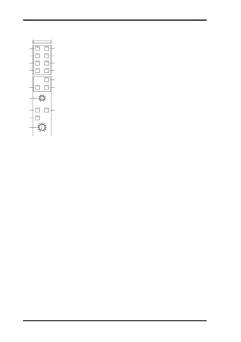
CONTROL ROOM
A
STEREO 2TR D1 button
This button selects the 2TR IN DIGITAL AES/EBU 1 as the Control Room Mon-
itor signal source. Its indicator lights up when this source is selected. See “Control
Room Monitoring” on page 158 for more information.
B
STEREO 2TR D2 button
This button selects the 2TR IN DIGITAL AES/EBU 2 as the Control Room Monitor
signal source. Its indicator lights up when this source is selected. See “Control
Room Monitoring” on page 158 for more information.
C
STEREO 2TR D3 button
This button selects the 2TR IN DIGITAL COAXIAL 3 as the Control Room Moni-
tor signal source. Its indicator lights up when this source is selected. See “Control
Room Monitoring” on page 158 for more information.
D
STEREO 2TR A1 button
This button selects the 2TR IN ANALOG 1 as the Control Room Monitor signal
source. Its indicator lights up when this source is selected. See “Control Room
Monitoring” on page 158 for more information.
E
STEREO 2TR A2 button
This button selects the 2TR IN ANALOG 2 as the Control Room Monitor signal
source. Its indicator lights up when this source is selected. See “Control Room
Monitoring” on page 158 for more information.
F
STEREO button
This button selects the Stereo Out as the Control Room Monitor signal source. Its indicator
lights up when this source is selected. See “Control Room Monitoring” on page 158 for
more information.
G
STEREO ASSIGN 1 button
This button is used to select the assigned Output Channel as the Control Room Monitor
signal source. Its indicator lights up when this source is selected. See “Control Room Setup”
on page 159 for more information.
H
STEREO ASSIGN 2 button
This button is used to select the assigned Output Channel as the Control Room Monitor
signal source. Its indicator lights up when this source is selected. See “Control Room Setup”
on page 159 for more information.
I
SURROUND BUS button
This button is used to select the Bus Outs as the Surround Monitor signal source. Its indi-
cator lights up when this source is selected. See “Surround Monitoring” on page 160 for
more information.
J
SURROUND ASSIGN 1 button
This button is used to select the assigned Slot’s Inputs as the Surround Monitor signal
source. Its indicator lights up when this source is selected. See “Surround Monitoring” on
page 160 for more information.
K
SURROUND ASSIGN 2 button
This button is used to select the assigned Slot’s Inputs as the Surround Monitor signal
source. Its indicator lights up when this source is selected. See “Surround Monitoring” on
page 160 for more information.
L
SURROUND MONITOR LEVEL control
This control is used to adjust the level of the Surround Monitor signals. See “Surround
Monitoring” on page 160 for more information.
CONTROL ROOM
2TR D1
2TR A1
2TR D2
2TR A2
2TR D3
STEREO
ASSIGN
1
ASSIGN
2
ASSIGN
1
ASSIGN
2
DIMMER
SMALL
MONO
SURROUND
MONITOR LEVEL
CONTROL ROOM LEVEL
BUS
STEREO
SURROUND
10
0
1
4
2
5
3
6
7
8
J
L
K
M
O
P
N
9
Кнопка STEREO
Выбирает выход Stereo Out в качестве источника сигнала Control Room Monitor. При вы-
боре данного источника загорается соответствующий индикатор. Информация о мони-
торинге аппаратной приведена на стр. 158.
Кнопка STEREO ASSIGN 1
Выбирает канал выхода в качестве источника сигнала Control Room Monitor. При выбо-
ре данного источника загорается соответствующий индикатор. Информация о настройки
аппаратной (Control Room Setup) приведена на стр. 159.
Кнопка STEREO ASSIGN 2
Выбирает канал выхода в качестве источника сигнала Control Room Monitor. При выбо-
ре данного источника загорается соответствующий индикатор. Информация о настройки
аппаратной (Control Room Setup) приведена на стр. 159.
Кнопка SURROUND BUS
Выбирает выход Bus Out в качестве источника сигнала Surround Monitor. При выборе
данного источника загорается соответствующий индикатор. Информация о мониторинге
окружающего звука (Surround Monitoring) приведена на стр. 160.
Кнопка SURROUND ASSIGN 1
Используется для выбора заданных Slot’s Inputs (входов слота) в качестве источникаа
сигнала Surround Monitor. При выборе данного источника загорается соответствующий
индикатор. Информация о мониторинге окружающего звука (Surround Monitoring) при-
ведена на стр. 160.
Кнопка SURROUND ASSIGN 2
Используется для выбора заданных Slot’s Inputs (входов слота) в качестве источникаа
сигнала Surround Monitor. При выборе данного источника загорается соответствующий
индикатор. Информация о мониторинге окружающего звука (Surround Monitoring) при-
ведена на стр. 160.
Кнопка STEREO 2TR D1
Выбирает 2TR IN DIGITAL AES/EBU 1 в качестве источника сигнала Control
Room Monitor. При выборе данного источника загорается соответствующий
индикатор. Информация о мониторинге аппаратной приведена на стр. 158.
Кнопка STEREO 2TR D2
Выбирает 2TR IN DIGITAL AES/EBU 2 в качестве источника сигнала Control
Room Monitor. При выборе данного источника загорается соответствующий
индикатор. Информация о мониторинге аппаратной приведена на стр. 158.
Кнопка STEREO 2TR D3
Выбирает 2TR IN DIGITAL COAXIAL 3 в качестве источника сигнала Control
Room Monitor. При выборе данного источника загорается соответствующий
индикатор. Информация о мониторинге аппаратной приведена на стр. 158.
Кнопка STEREO 2TR А1
Выбирает 2TR IN ANALOG 1 в качестве источника сигнала Control Room
Monitor. При выборе данного источника загорается соответствующий инди-
катор. Информация о мониторинге аппаратной приведена на стр. 158.
Кнопка STEREO 2TR А2
Выбирает 2TR IN ANALOG 2 в качестве источника сигнала Control Room
Monitor. При выборе данного источника загорается соответствующий инди-
катор. Информация о мониторинге аппаратной приведена на стр. 158.