Маршрутизация, Routing, Маршрутизация входного сигнала – Инструкция по эксплуатации Yamaha sp2060
Страница 26: Input routing, Output routing, Маршрутизация выхода
Предисловие
Введение
в SP2060
Регуляторы
и подключения
Работа
с панелью
Настройки
сети
Справочники
26
SP2060 Руководство пользователя
Работа с панелью
Маршрутизация
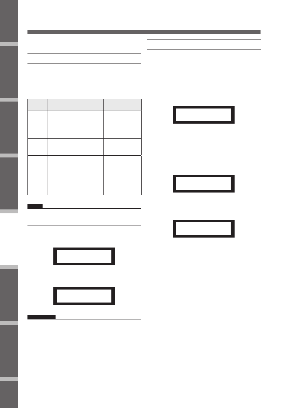
Маршрутизация входного сигнала
Можно выбрать в качестве входного аналоговый или цифро-
вой сигналы. Этот выбор привязывается к мастернастройке
синхронизации. Можно также маршрутизировать левый ка-
нал входного сигнала, принятый на разъеме [INPUT A] или
[DIGITAL IN] на оба входных канала А и В.
Опция
Выбор входного сигнала
Мастер
синхронизации
ANA A/B
Сигнал на разъеме [INPUT
A] маршрутизируется на ка-
нал А, а сигнал на разъеме
[INPUT B] маршрутизирует-
ся на канал В.
Встроенная синх-
ронизация: 96kHz
ANA A/A
Сигнал на разъеме [INPUT
A] маршрутизируется на
каналы А и В
DIG L/R
Сигнал левого канала мар-
шрутизируется на канал А, и
сигнал правого канала – на
канал В.
Входящий сигнал
AES/ EBU
DIG L/L
Сигнал левого канала мар-
шрутизируется на каналы
А и В.
СОВЕТ:
Статус включения синхронизации выбирается на экране
дисплея Utility. (стр. 36).
Нажмите на клавишу [ROUTING] для выбора
экрана Routing (Маршрутизация).
Ref
erences
Intr
oduction
to the SP2060
Fore
w
or
d
The Contr
ols
and Connector
s
Netw
ork Settings
P
anel Operation
Panel Operation
SP2060 Owner’s Manual
27
ROUTING
Input routing
You can select either analog or digital input signals. This se-
lection links to the word clock master setting. You can also
route the left channel of an input signal received at the [IN-
PUT A] or [DIGITAL IN] connector to both Input chan-
nels A and B.
1.
Press the [ROUTING] key to select the
Routing display.
2.
Press the [▲INC]/[▼DEC] keys to select an
input signal source.
Output routing
You can route Input channel A, B, and SUM signals to the
Crossover input.
The following three channels are available:
• IN A
• IN SUM
• IN B
1.
Press the [ROUTING] key to select the
Routing display.
2.
Press the [SEL] key for the target Output
channel.
The [SEL] key LED for the selected channel lights up.
The [SEL] key LED for each channel that shares the
same component flashes. The selected channel name ap-
pears on the display.
3.
Press the [▲INC]/[▼DEC] keys to select an
input source to be routed to the Crossover.
Option
Input Signal Selection
Word Clock
Master
ANA A/B
A signal at the [INPUT A]
connector is routed to
channel A, and a signal at
the [INPUT B] connector
to channel B.
Internal clock:
96kHz
ANA A/A
A signal at the [INPUT A]
connector is routed to
channels A and B.
DIG L/R
A left channel signal is
routed to channel A, and
a right channel signal to
channel B.
Incoming AES/
EBU signal
DIG L/L
A left channel signal is
routed to channels A and
B.
HINT
You can check the word clock status on the Utility display. See
page 37.
NOTE
Signals are muted while they are switched between analog and
digital to avoid noise.
INPUT SELECT
SOURCE = ANA A/B
INPUT SELECT
SOURCE = ANA A/A
OUT 2
SOURCE = IN A
OUT 4
SOURCE = IN A
OUT 4
SOURCE = IN SUM
Нажмите на клавиши [
/
INC]/[
\
DEC] для
выбора источника входного сигнала.
Ref
erences
Intr
oduction
to the SP2060
Fore
w
or
d
The Contr
ols
and Connector
s
Netw
ork Settings
P
anel Operation
Panel Operation
SP2060 Owner’s Manual
27
ROUTING
Input routing
You can select either analog or digital input signals. This se-
lection links to the word clock master setting. You can also
route the left channel of an input signal received at the [IN-
PUT A] or [DIGITAL IN] connector to both Input chan-
nels A and B.
1.
Press the [ROUTING] key to select the
Routing display.
2.
Press the [▲INC]/[▼DEC] keys to select an
input signal source.
Output routing
You can route Input channel A, B, and SUM signals to the
Crossover input.
The following three channels are available:
• IN A
• IN SUM
• IN B
1.
Press the [ROUTING] key to select the
Routing display.
2.
Press the [SEL] key for the target Output
channel.
The [SEL] key LED for the selected channel lights up.
The [SEL] key LED for each channel that shares the
same component flashes. The selected channel name ap-
pears on the display.
3.
Press the [▲INC]/[▼DEC] keys to select an
input source to be routed to the Crossover.
Option
Input Signal Selection
Word Clock
Master
ANA A/B
A signal at the [INPUT A]
connector is routed to
channel A, and a signal at
the [INPUT B] connector
to channel B.
Internal clock:
96kHz
ANA A/A
A signal at the [INPUT A]
connector is routed to
channels A and B.
DIG L/R
A left channel signal is
routed to channel A, and
a right channel signal to
channel B.
Incoming AES/
EBU signal
DIG L/L
A left channel signal is
routed to channels A and
B.
HINT
You can check the word clock status on the Utility display. See
page 37.
NOTE
Signals are muted while they are switched between analog and
digital to avoid noise.
INPUT SELECT
SOURCE = ANA A/B
INPUT SELECT
SOURCE = ANA A/A
OUT 2
SOURCE = IN A
OUT 4
SOURCE = IN A
OUT 4
SOURCE = IN SUM
ПРИМЕЧАНИЕ:
При переключении между аналоговым и цифровым входом
выполняется мьютирование сигнала во избежание появле-
ния шума.
Маршрутизация выхода
Можно выполнить маршрутизацию сигналов входных кана-
лов А, В, и SUM на вход Кроссовера.
Возможны следующие каналы:
• IN A
• IN SUM
• IN B
Нажмите на клавишу [ROUTING] для выбора
экрана Routing (Маршрутизация).
Ref
erences
Intr
oduction
to the SP2060
Fore
w
or
d
The Contr
ols
and Connector
s
Netw
ork Settings
P
anel Operation
Panel Operation
SP2060 Owner’s Manual
27
ROUTING
Input routing
You can select either analog or digital input signals. This se-
lection links to the word clock master setting. You can also
route the left channel of an input signal received at the [IN-
PUT A] or [DIGITAL IN] connector to both Input chan-
nels A and B.
1.
Press the [ROUTING] key to select the
Routing display.
2.
Press the [▲INC]/[▼DEC] keys to select an
input signal source.
Output routing
You can route Input channel A, B, and SUM signals to the
Crossover input.
The following three channels are available:
• IN A
• IN SUM
• IN B
1.
Press the [ROUTING] key to select the
Routing display.
2.
Press the [SEL] key for the target Output
channel.
The [SEL] key LED for the selected channel lights up.
The [SEL] key LED for each channel that shares the
same component flashes. The selected channel name ap-
pears on the display.
3.
Press the [▲INC]/[▼DEC] keys to select an
input source to be routed to the Crossover.
Option
Input Signal Selection
Word Clock
Master
ANA A/B
A signal at the [INPUT A]
connector is routed to
channel A, and a signal at
the [INPUT B] connector
to channel B.
Internal clock:
96kHz
ANA A/A
A signal at the [INPUT A]
connector is routed to
channels A and B.
DIG L/R
A left channel signal is
routed to channel A, and
a right channel signal to
channel B.
Incoming AES/
EBU signal
DIG L/L
A left channel signal is
routed to channels A and
B.
HINT
You can check the word clock status on the Utility display. See
page 37.
NOTE
Signals are muted while they are switched between analog and
digital to avoid noise.
INPUT SELECT
SOURCE = ANA A/B
INPUT SELECT
SOURCE = ANA A/A
OUT 2
SOURCE = IN A
OUT 4
SOURCE = IN A
OUT 4
SOURCE = IN SUM
Нажмите на клавишу [SEL] для выбора нуж-
ного канала выхода.
Клавиша [SEL] выбранного канала будет светиться.
Светодиодный индикатор клавиши [SEL] каждого
канала, являющегося частью этого же компонента
также мигает. На дисплее появляется имя выбранного
канала.
Ref
erences
Intr
oduction
to the SP2060
Fore
w
or
d
The Contr
ols
and Connector
s
Netw
ork Settings
P
anel Operation
Panel Operation
SP2060 Owner’s Manual
27
ROUTING
Input routing
You can select either analog or digital input signals. This se-
lection links to the word clock master setting. You can also
route the left channel of an input signal received at the [IN-
PUT A] or [DIGITAL IN] connector to both Input chan-
nels A and B.
1.
Press the [ROUTING] key to select the
Routing display.
2.
Press the [▲INC]/[▼DEC] keys to select an
input signal source.
Output routing
You can route Input channel A, B, and SUM signals to the
Crossover input.
The following three channels are available:
• IN A
• IN SUM
• IN B
1.
Press the [ROUTING] key to select the
Routing display.
2.
Press the [SEL] key for the target Output
channel.
The [SEL] key LED for the selected channel lights up.
The [SEL] key LED for each channel that shares the
same component flashes. The selected channel name ap-
pears on the display.
3.
Press the [▲INC]/[▼DEC] keys to select an
input source to be routed to the Crossover.
Option
Input Signal Selection
Word Clock
Master
ANA A/B
A signal at the [INPUT A]
connector is routed to
channel A, and a signal at
the [INPUT B] connector
to channel B.
Internal clock:
96kHz
ANA A/A
A signal at the [INPUT A]
connector is routed to
channels A and B.
DIG L/R
A left channel signal is
routed to channel A, and
a right channel signal to
channel B.
Incoming AES/
EBU signal
DIG L/L
A left channel signal is
routed to channels A and
B.
HINT
You can check the word clock status on the Utility display. See
page 37.
NOTE
Signals are muted while they are switched between analog and
digital to avoid noise.
INPUT SELECT
SOURCE = ANA A/B
INPUT SELECT
SOURCE = ANA A/A
OUT 2
SOURCE = IN A
OUT 4
SOURCE = IN A
OUT 4
SOURCE = IN SUM
Нажмите на клавиши [
/
INC]/[
\
DEC] для
выбора источника входного сигнала, марш-
рутизируемого на Кроссовер.
Ref
erences
Intr
oduction
to the SP2060
Fore
w
or
d
The Contr
ols
and Connector
s
Netw
ork Settings
P
anel Operation
Panel Operation
SP2060 Owner’s Manual
27
ROUTING
Input routing
You can select either analog or digital input signals. This se-
lection links to the word clock master setting. You can also
route the left channel of an input signal received at the [IN-
PUT A] or [DIGITAL IN] connector to both Input chan-
nels A and B.
1.
Press the [ROUTING] key to select the
Routing display.
2.
Press the [▲INC]/[▼DEC] keys to select an
input signal source.
Output routing
You can route Input channel A, B, and SUM signals to the
Crossover input.
The following three channels are available:
• IN A
• IN SUM
• IN B
1.
Press the [ROUTING] key to select the
Routing display.
2.
Press the [SEL] key for the target Output
channel.
The [SEL] key LED for the selected channel lights up.
The [SEL] key LED for each channel that shares the
same component flashes. The selected channel name ap-
pears on the display.
3.
Press the [▲INC]/[▼DEC] keys to select an
input source to be routed to the Crossover.
Option
Input Signal Selection
Word Clock
Master
ANA A/B
A signal at the [INPUT A]
connector is routed to
channel A, and a signal at
the [INPUT B] connector
to channel B.
Internal clock:
96kHz
ANA A/A
A signal at the [INPUT A]
connector is routed to
channels A and B.
DIG L/R
A left channel signal is
routed to channel A, and
a right channel signal to
channel B.
Incoming AES/
EBU signal
DIG L/L
A left channel signal is
routed to channels A and
B.
HINT
You can check the word clock status on the Utility display. See
page 37.
NOTE
Signals are muted while they are switched between analog and
digital to avoid noise.
INPUT SELECT
SOURCE = ANA A/B
INPUT SELECT
SOURCE = ANA A/A
OUT 2
SOURCE = IN A
OUT 4
SOURCE = IN A
OUT 4
SOURCE = IN SUM