The rpx400 and recording, Line usb source mapping, Направление линейного сигнала – Инструкция по эксплуатации DigiTech rpx400
Страница 30: Mic usb source mapping, Line signal routing, Linoff, Lindry, Linrvb, Linefx
Line USB Source Mapping
Как видно из предыдущей диаграммы, линейный сигнал поступает в USB-порт
компьютера по двум направлениям. На Пути
A линейный сигнал изолируется
непосредственно на линейном входе, после чего направляется на USB-порт без
обработки. Путь С разделяет сигнал уже на выходе из RPx400, что позволяет добавлять
к звуку любой набор эффектов. На схеме ниже показано место изоляции сигнала в
зависимости от используемой конфигурации настроек
Line, USB 1-2 Source и USB 3-4
Source.
Mic USB Source Mapping
The mic signal, as can be seen in the previous Mic Signal Routing diagram, has two paths in which it can
travel up the USB port to the computer. Path E taps the mic signal off right at the mic input and sends
unprocessed signal up to the USB port. Path C taps the signal at the output of the RPx400 and can
include any effects processing that may be used. Below is a matrix to show where the signal is tapped
based on how the Mic, USB 1-2 Source, and USB 3-4 Source settings are configured.
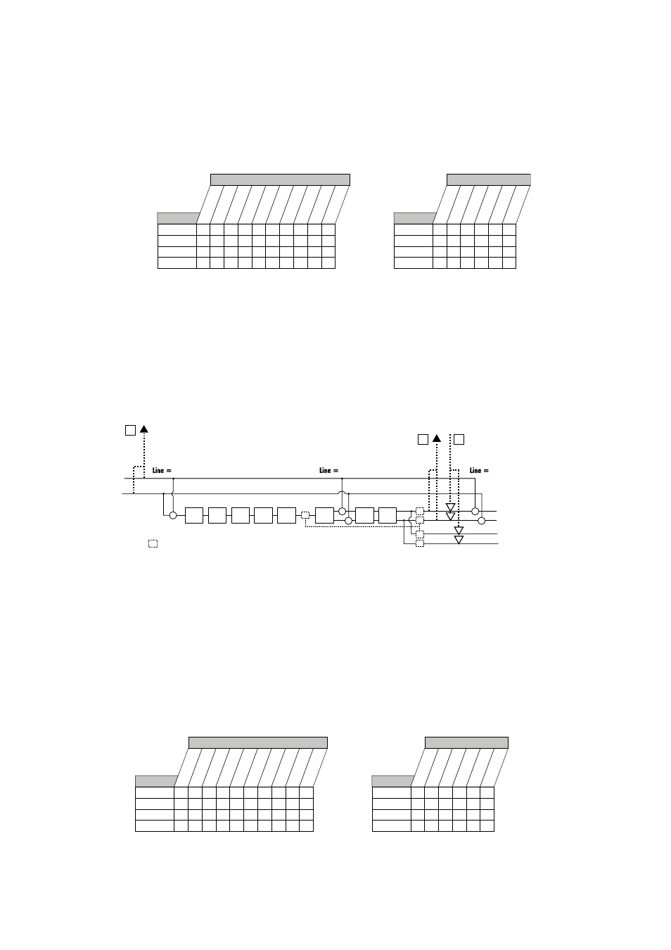
Line Signal Routing
The line signals, like the mic signal, can be routed in different ways through the RPx400.
linoff
disables
the line inputs from being being heard but dry line signal can still be recorded.
lindry
routes the left
and right line signals around the RPx400’s effects processing and mixes them in at the left and right out-
puts respectively.
linrvb
routes the line signals only through the RPx400 Delay and Reverb modules.
linefx
sums the left and right line input signals together and then routes this signal through all of the
RPx400’s effects.
Line USB Source Mapping
The line input signals, as can be seen in the previous Line Signal Routing diagram, has two paths in which
they can travel up the USB port to the computer. Path A taps the line input signals off right at the line
input and sends unprocessed signal up to the USB port. Path B taps these signals at the output of the
RPx400 and can include any effects processing that may be used. Below is a matrix to show where the
signal is tapped based on how the Line, USB 1-2 Source, and USB 3-4 Source settings are
configured.
of
f
dg
tr
+m
dr
yl
in
dr
yg
tr
dr
ymic
dr
ums
USB 3-4 Source
•
• F •
•
•
•
• F •
•
•
•
• C •
•
•
•
• C •
•
•
stereo MO
NO
SU
M+D
G
SU
MMI
C
DG
TR
+M
dry
li
n
DRYGT
R
DRYMI
C
DRUMS reamp
LINoff
LINdry
LINRVB
LINeFX
Line
USB 1-2 Source
Routing of Line Inputs to USB
F F F F • F •
•
•
•
F F F F • F •
•
•
•
C C C C • C •
•
•
•
C C C C • C •
•
•
•
LINoff
LINdry
LINRVB
LINeFX
Line
Line Left
Line Right
linefx
linrvb
lindry
+
Pickup
Sim
Wah
Comp
Amp/
Cabinet
EQ
Noise
Gate
Mod/
Chorus
Delay
Reverb
SC
+
+
+
+
SC
SC
XLR Left Output
XLR Right Output
1/4" Left Output
1/4" Right Output
SC
SC
= Speaker Compensation Module
SC
(1/4" USB Playback
disabled in Split Modes)
USB Dry
Send Path
F
USB Send
Path
C
USB Playback
Return Path
D
stereo MO
NO
SUM+D
G
SU
MM
IC
DG
TR
+M
dr
yl
in
DRYGT
R
DRYMI
C
DRUMS reamp
micoff
micdry
micRVB
MICFX
Mic
USB 1-2 Source
E E E E E •
• E •
•
E E E E E •
• E •
•
C C C E E •
• E •
•
C C C E E •
• E •
•
Routing of Mic Inputs to USB
of
f
dg
tr
+m
dr
yl
in
dr
yg
tr
dr
ymic
dr
ums
micoff
micdry
micRVB
MICFX
Mic
USB 3-4 Source
• E •
• E •
• E •
• E •
• E •
• E •
• E •
• E •
29
The RPx400 and Recording
Mic USB Source Mapping
Как видно из предыдущей диаграммы, сигнал микрофона поступает в USB-порт
компьютера по двум направлениям. На Пути
Е сигнал микрофона изолируется
непосредственно на входе, после чего направляется на USB-порт без обработки. Путь
С разделяет сигнал уже на выходе из RPx400, что позволяет добавлять к звуку любой
набор эффектов. На схеме ниже показано место изоляции сигнала в зависимости от
используемой конфигурации настроек
Mic, USB 1-2 Source и USB 3-4 Source.
Направление линейного сигнала
Линейный сигнал, также как и сигнал микрофона, может быть пропущен через RPx400
различными способами. В режиме LINOFF линейные сигналы не слышны, однако их
можно записывать. В режиме LINDRY сигнал c левого и правого входов поступает
на выходы, минуя обработку эффектами. LINRVB пропускает линейный сигнал через
модули Delay и Reverb RPx400. В режиме LINEFX левый и правый сигналы суммируются в
моно-сигнал, который может быть обработан всеми эффектами процессора.
Mic USB Source Mapping
The mic signal, as can be seen in the previous Mic Signal Routing diagram, has two paths in which it can
travel up the USB port to the computer. Path E taps the mic signal off right at the mic input and sends
unprocessed signal up to the USB port. Path C taps the signal at the output of the RPx400 and can
include any effects processing that may be used. Below is a matrix to show where the signal is tapped
based on how the Mic, USB 1-2 Source, and USB 3-4 Source settings are configured.
Line Signal Routing
The line signals, like the mic signal, can be routed in different ways through the RPx400.
linoff
disables
the line inputs from being being heard but dry line signal can still be recorded.
lindry
routes the left
and right line signals around the RPx400’s effects processing and mixes them in at the left and right out-
puts respectively.
linrvb
routes the line signals only through the RPx400 Delay and Reverb modules.
linefx
sums the left and right line input signals together and then routes this signal through all of the
RPx400’s effects.
Line USB Source Mapping
The line input signals, as can be seen in the previous Line Signal Routing diagram, has two paths in which
they can travel up the USB port to the computer. Path A taps the line input signals off right at the line
input and sends unprocessed signal up to the USB port. Path B taps these signals at the output of the
RPx400 and can include any effects processing that may be used. Below is a matrix to show where the
signal is tapped based on how the Line, USB 1-2 Source, and USB 3-4 Source settings are
configured.
of
f
dg
tr
+m
dr
yl
in
dr
yg
tr
dr
ymic
dr
ums
USB 3-4 Source
•
• F •
•
•
•
• F •
•
•
•
• C •
•
•
•
• C •
•
•
stereo MO
NO
SU
M+D
G
SU
MMI
C
DG
TR
+M
dry
li
n
DRYGT
R
DRYMI
C
DRUMS reamp
LINoff
LINdry
LINRVB
LINeFX
Line
USB 1-2 Source
Routing of Line Inputs to USB
F F F F • F •
•
•
•
F F F F • F •
•
•
•
C C C C • C •
•
•
•
C C C C • C •
•
•
•
LINoff
LINdry
LINRVB
LINeFX
Line
Line Left
Line Right
linefx
linrvb
lindry
+
Pickup
Sim
Wah
Comp
Amp/
Cabinet
EQ
Noise
Gate
Mod/
Chorus
Delay
Reverb
SC
+
+
+
+
SC
SC
XLR Left Output
XLR Right Output
1/4" Left Output
1/4" Right Output
SC
SC
= Speaker Compensation Module
SC
(1/4" USB Playback
disabled in Split Modes)
USB Dry
Send Path
F
USB Send
Path
C
USB Playback
Return Path
D
stereo MO
NO
SUM+D
G
SU
MM
IC
DG
TR
+M
dr
yl
in
DRYGT
R
DRYMI
C
DRUMS reamp
micoff
micdry
micRVB
MICFX
Mic
USB 1-2 Source
E E E E E •
• E •
•
E E E E E •
• E •
•
C C C E E •
• E •
•
C C C E E •
• E •
•
Routing of Mic Inputs to USB
of
f
dg
tr
+m
dr
yl
in
dr
yg
tr
dr
ymic
dr
ums
micoff
micdry
micRVB
MICFX
Mic
USB 3-4 Source
• E •
• E •
• E •
• E •
• E •
• E •
• E •
• E •
29
The RPx400 and Recording
Mic USB Source Mapping
The mic signal, as can be seen in the previous Mic Signal Routing diagram, has two paths in which it can
travel up the USB port to the computer. Path E taps the mic signal off right at the mic input and sends
unprocessed signal up to the USB port. Path C taps the signal at the output of the RPx400 and can
include any effects processing that may be used. Below is a matrix to show where the signal is tapped
based on how the Mic, USB 1-2 Source, and USB 3-4 Source settings are configured.
Line Signal Routing
The line signals, like the mic signal, can be routed in different ways through the RPx400.
linoff
disables
the line inputs from being being heard but dry line signal can still be recorded.
lindry
routes the left
and right line signals around the RPx400’s effects processing and mixes them in at the left and right out-
puts respectively.
linrvb
routes the line signals only through the RPx400 Delay and Reverb modules.
linefx
sums the left and right line input signals together and then routes this signal through all of the
RPx400’s effects.
Line USB Source Mapping
The line input signals, as can be seen in the previous Line Signal Routing diagram, has two paths in which
they can travel up the USB port to the computer. Path A taps the line input signals off right at the line
input and sends unprocessed signal up to the USB port. Path B taps these signals at the output of the
RPx400 and can include any effects processing that may be used. Below is a matrix to show where the
signal is tapped based on how the Line, USB 1-2 Source, and USB 3-4 Source settings are
configured.
of
f
dg
tr
+m
dr
yl
in
dr
yg
tr
dr
ymic
dr
ums
USB 3-4 Source
•
• F •
•
•
•
• F •
•
•
•
• C •
•
•
•
• C •
•
•
stereo MO
NO
SU
M+D
G
SU
MMI
C
DG
TR
+M
dry
li
n
DRYGT
R
DRYMI
C
DRUMS reamp
LINoff
LINdry
LINRVB
LINeFX
Line
USB 1-2 Source
Routing of Line Inputs to USB
F F F F • F •
•
•
•
F F F F • F •
•
•
•
C C C C • C •
•
•
•
C C C C • C •
•
•
•
LINoff
LINdry
LINRVB
LINeFX
Line
Line Left
Line Right
linefx
linrvb
lindry
+
Pickup
Sim
Wah
Comp
Amp/
Cabinet
EQ
Noise
Gate
Mod/
Chorus
Delay
Reverb
SC
+
+
+
+
SC
SC
XLR Left Output
XLR Right Output
1/4" Left Output
1/4" Right Output
SC
SC
= Speaker Compensation Module
SC
(1/4" USB Playback
disabled in Split Modes)
USB Dry
Send Path
F
USB Send
Path
C
USB Playback
Return Path
D
stereo MO
NO
SUM+D
G
SU
MM
IC
DG
TR
+M
dr
yl
in
DRYGT
R
DRYMI
C
DRUMS reamp
micoff
micdry
micRVB
MICFX
Mic
USB 1-2 Source
E E E E E •
• E •
•
E E E E E •
• E •
•
C C C E E •
• E •
•
C C C E E •
• E •
•
Routing of Mic Inputs to USB
of
f
dg
tr
+m
dr
yl
in
dr
yg
tr
dr
ymic
dr
ums
micoff
micdry
micRVB
MICFX
Mic
USB 3-4 Source
• E •
• E •
• E •
• E •
• E •
• E •
• E •
• E •
29
The RPx400 and Recording