X-over (кроссовер), X-over (crossover), Настройка кроссовера – Инструкция по эксплуатации Yamaha sp2060
Страница 27: Setting the crossover
Предисловие
Введение
в SP2060
Регуляторы
и подключения
Работа
с панелью
Настройки
сети
Справочники
SP2060 Руководство пользователя
27
Работа с панелью
X-OVER (Кроссовер)
Настройка кроссовера
Входные сигналы могут быть на выходе разделены на опре-
деленные частотные диапазоны в зависимости от частотных
характеристик громкоговорителей. Количество разделений
составляет от 1 полосы до 6 в зависимости от выбранного
компонента.
Параметр Диапазон
Функция
LEVEL
–
∞, –138.00
до +10.00dB
Регулирует уровень входного
сигнала на кроссовер. Для
выходных каналов компонента
используется такая же настрой-
ка уровня.
POLARITY
NORMAL
INVERTED
Инвертирование фазы вы-
ходного сигнала для каждого
частотного диапазона.
HPF
См. шаг 4.
LPF
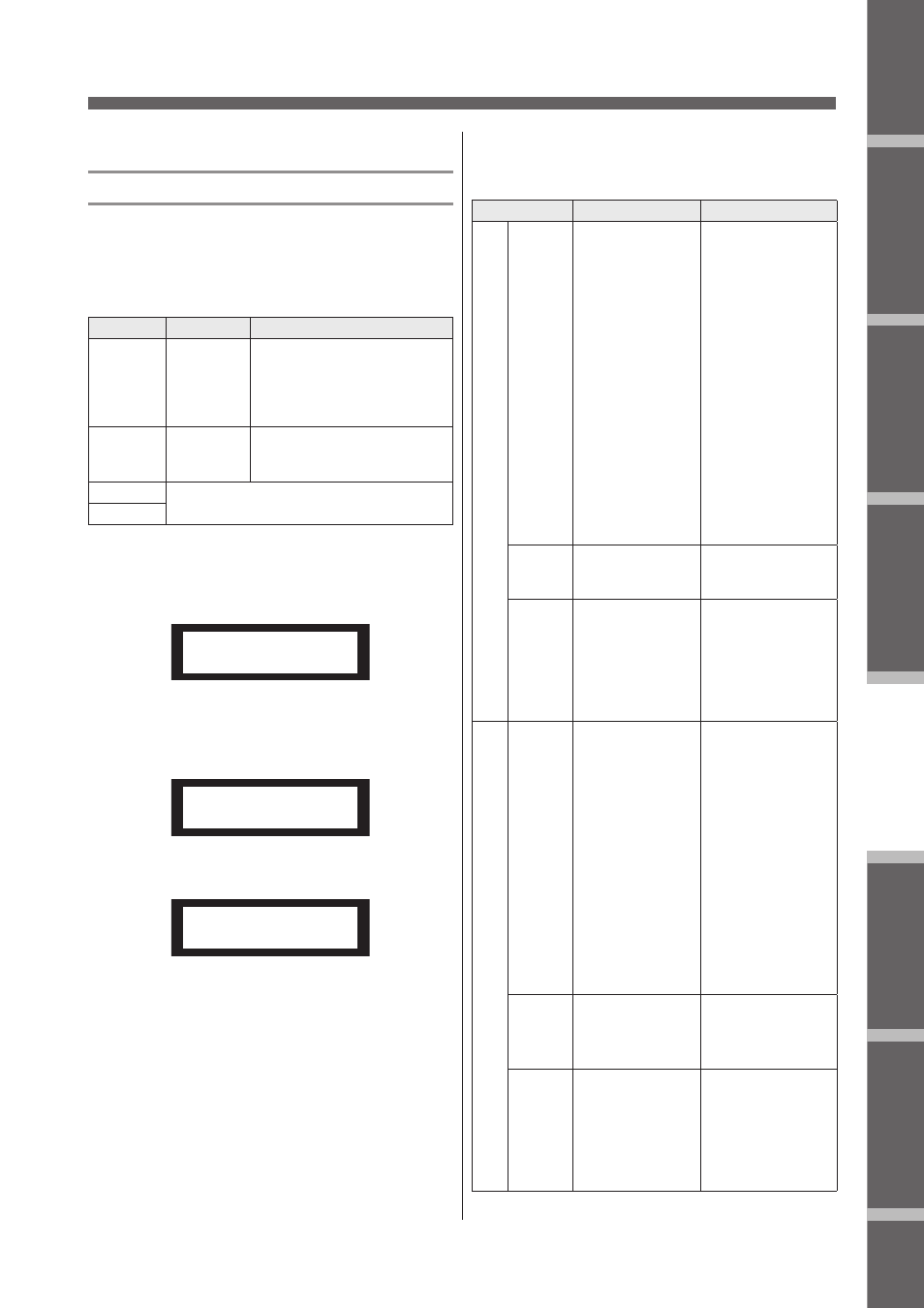
1.
Нажмите повторно на клавишу [X-OVER]
до тех пор, пока на дисплее не появится
экран X-Over.
Panel Operation
SP2060 Owner’s Manual
Fore
w
or
d
Netw
ork Settings
Ref
erences
P
anel Operation
Intr
oduction
to the SP2060
The Contr
ols
and Connector
s
28
X-OVER (Crossover)
Setting the Crossover
Input signals can be divided into specified frequency ranges
to suit speaker response characteristics prior to output.
The number of division is determined to 1-way through 6-
way, depending on the selected component.
1.
Press the [X-OVER] key repeatedly until the X-
Over display appears on the screen.
2.
Press the [SEL] key for the target Output
channel.
The [SEL] key LED of the selected channel lights up,
and the corresponding channel name is displayed.
3.
Press the [NEXT]/[BACK] keys to select a
parameter to edit.
4.
Press the [▲INC]/[▼DEC] keys to set the
parameter value.
Parameter
Range
Function
LEVEL
–
∞
, –138.00 through
+10.00dB
Adjusts the level of the
signal input to the
Crossover. The same
Level setting is used
for the output channels
of a component.
POLARITY
NORMAL
INVERTED
The output signal
phase for each
frequency range is
inverted.
HPF
Refer to Step 4.
LPF
OUT 1 LPF
FREQ = 20.0kHz
OUT 3 LPF
FREQ = 20.0kHz
OUT 3 LPF
TYPE =24AdjustGc
Parameter
Range
Function
HPF
TYPE
Thru
6dB/Oct
12dB/Oct AdjustGc
12dB/Oct Butrwrth
12dB/Oct Bessel
12dB/Oct Linkwitz
18dB/Oct AdjustGc
18dB/Oct Butrwrth
18dB/Oct Bessel
24dB/Oct AdjustGc
24dB/Oct Butrwrth
24dB/Oct Bessel
24dB/Oct Linkwitz
36dB/Oct AdjustGc
36dB/Oct Butrwrth
36dB/Oct Bessel
48dB/Oct AdjustGc
48dB/Oct Butrwrth
48dB/Oct Bessel
48dB/Oct Linkwitz
Selects an
attenuation
amount per
octave, and a
type of filter.
If you select
“Thru,” no filter
will be applied.
FREQ
(Frequency)
20.0Hz–20.0kHz
Specifies the
cutoff frequency
of the high pass
filter.
Gc
–6dB through +6dB
You can set the
gain for the cutoff
frequency (Gc)
when you select
“AdjustGc
(Adjustable Gc)”
for the Type
parameter.
LPF
TYPE
Thru
6dB/Oct
12dB/Oct AdjustGc
12dB/Oct Butrwrth
12dB/Oct Bessel
12dB/Oct Linkwitz
18dB/Oct AdjustGc
18dB/Oct Butrwrth
18dB/Oct Bessel
24dB/Oct AdjustGc
24dB/Oct Butrwrth
24dB/Oct Bessel
24dB/Oct Linkwitz
36dB/Oct AdjustGc
36dB/Oct Butrwrth
36dB/Oct Bessel
48dB/Oct AdjustGc
48dB/Oct Butrwrth
48dB/Oct Bessel
48dB/Oct Linkwitz
Selects an
attenuation
amount per
octave, and a
type of filter.
If you select
“Thru,” no filter
will be applied.
FREQ
(Frequency)
20.0Hz–20.0kHz
Specifies the
cutoff frequency
of the low pass
filter.
Gc
–6dB through +6dB
You can set the
gain for the cutoff
frequency (Gc)
when you select
“AdjustGc
(Adjustable Gc)”
for the Type
parameter.
2.
Нажмите на клавишу [SEL] для выбора
нужного канала выхода.
Клавиша [SEL] выбранного канала загорится, и на
экране будет выведено имя соответствующего канала.
Panel Operation
SP2060 Owner’s Manual
Fore
w
or
d
Netw
ork Settings
Ref
erences
P
anel Operation
Intr
oduction
to the SP2060
The Contr
ols
and Connector
s
28
X-OVER (Crossover)
Setting the Crossover
Input signals can be divided into specified frequency ranges
to suit speaker response characteristics prior to output.
The number of division is determined to 1-way through 6-
way, depending on the selected component.
1.
Press the [X-OVER] key repeatedly until the X-
Over display appears on the screen.
2.
Press the [SEL] key for the target Output
channel.
The [SEL] key LED of the selected channel lights up,
and the corresponding channel name is displayed.
3.
Press the [NEXT]/[BACK] keys to select a
parameter to edit.
4.
Press the [▲INC]/[▼DEC] keys to set the
parameter value.
Parameter
Range
Function
LEVEL
–
∞
, –138.00 through
+10.00dB
Adjusts the level of the
signal input to the
Crossover. The same
Level setting is used
for the output channels
of a component.
POLARITY
NORMAL
INVERTED
The output signal
phase for each
frequency range is
inverted.
HPF
Refer to Step 4.
LPF
OUT 1 LPF
FREQ = 20.0kHz
OUT 3 LPF
FREQ = 20.0kHz
OUT 3 LPF
TYPE =24AdjustGc
Parameter
Range
Function
HPF
TYPE
Thru
6dB/Oct
12dB/Oct AdjustGc
12dB/Oct Butrwrth
12dB/Oct Bessel
12dB/Oct Linkwitz
18dB/Oct AdjustGc
18dB/Oct Butrwrth
18dB/Oct Bessel
24dB/Oct AdjustGc
24dB/Oct Butrwrth
24dB/Oct Bessel
24dB/Oct Linkwitz
36dB/Oct AdjustGc
36dB/Oct Butrwrth
36dB/Oct Bessel
48dB/Oct AdjustGc
48dB/Oct Butrwrth
48dB/Oct Bessel
48dB/Oct Linkwitz
Selects an
attenuation
amount per
octave, and a
type of filter.
If you select
“Thru,” no filter
will be applied.
FREQ
(Frequency)
20.0Hz–20.0kHz
Specifies the
cutoff frequency
of the high pass
filter.
Gc
–6dB through +6dB
You can set the
gain for the cutoff
frequency (Gc)
when you select
“AdjustGc
(Adjustable Gc)”
for the Type
parameter.
LPF
TYPE
Thru
6dB/Oct
12dB/Oct AdjustGc
12dB/Oct Butrwrth
12dB/Oct Bessel
12dB/Oct Linkwitz
18dB/Oct AdjustGc
18dB/Oct Butrwrth
18dB/Oct Bessel
24dB/Oct AdjustGc
24dB/Oct Butrwrth
24dB/Oct Bessel
24dB/Oct Linkwitz
36dB/Oct AdjustGc
36dB/Oct Butrwrth
36dB/Oct Bessel
48dB/Oct AdjustGc
48dB/Oct Butrwrth
48dB/Oct Bessel
48dB/Oct Linkwitz
Selects an
attenuation
amount per
octave, and a
type of filter.
If you select
“Thru,” no filter
will be applied.
FREQ
(Frequency)
20.0Hz–20.0kHz
Specifies the
cutoff frequency
of the low pass
filter.
Gc
–6dB through +6dB
You can set the
gain for the cutoff
frequency (Gc)
when you select
“AdjustGc
(Adjustable Gc)”
for the Type
parameter.
3.
Для выбора редактируемого параметра
нажмите на клавиши [NEXT]/[BACK].
Panel Operation
SP2060 Owner’s Manual
Fore
w
or
d
Netw
ork Settings
Ref
erences
P
anel Operation
Intr
oduction
to the SP2060
The Contr
ols
and Connector
s
28
X-OVER (Crossover)
Setting the Crossover
Input signals can be divided into specified frequency ranges
to suit speaker response characteristics prior to output.
The number of division is determined to 1-way through 6-
way, depending on the selected component.
1.
Press the [X-OVER] key repeatedly until the X-
Over display appears on the screen.
2.
Press the [SEL] key for the target Output
channel.
The [SEL] key LED of the selected channel lights up,
and the corresponding channel name is displayed.
3.
Press the [NEXT]/[BACK] keys to select a
parameter to edit.
4.
Press the [▲INC]/[▼DEC] keys to set the
parameter value.
Parameter
Range
Function
LEVEL
–
∞
, –138.00 through
+10.00dB
Adjusts the level of the
signal input to the
Crossover. The same
Level setting is used
for the output channels
of a component.
POLARITY
NORMAL
INVERTED
The output signal
phase for each
frequency range is
inverted.
HPF
Refer to Step 4.
LPF
OUT 1 LPF
FREQ = 20.0kHz
OUT 3 LPF
FREQ = 20.0kHz
OUT 3 LPF
TYPE =24AdjustGc
Parameter
Range
Function
HPF
TYPE
Thru
6dB/Oct
12dB/Oct AdjustGc
12dB/Oct Butrwrth
12dB/Oct Bessel
12dB/Oct Linkwitz
18dB/Oct AdjustGc
18dB/Oct Butrwrth
18dB/Oct Bessel
24dB/Oct AdjustGc
24dB/Oct Butrwrth
24dB/Oct Bessel
24dB/Oct Linkwitz
36dB/Oct AdjustGc
36dB/Oct Butrwrth
36dB/Oct Bessel
48dB/Oct AdjustGc
48dB/Oct Butrwrth
48dB/Oct Bessel
48dB/Oct Linkwitz
Selects an
attenuation
amount per
octave, and a
type of filter.
If you select
“Thru,” no filter
will be applied.
FREQ
(Frequency)
20.0Hz–20.0kHz
Specifies the
cutoff frequency
of the high pass
filter.
Gc
–6dB through +6dB
You can set the
gain for the cutoff
frequency (Gc)
when you select
“AdjustGc
(Adjustable Gc)”
for the Type
parameter.
LPF
TYPE
Thru
6dB/Oct
12dB/Oct AdjustGc
12dB/Oct Butrwrth
12dB/Oct Bessel
12dB/Oct Linkwitz
18dB/Oct AdjustGc
18dB/Oct Butrwrth
18dB/Oct Bessel
24dB/Oct AdjustGc
24dB/Oct Butrwrth
24dB/Oct Bessel
24dB/Oct Linkwitz
36dB/Oct AdjustGc
36dB/Oct Butrwrth
36dB/Oct Bessel
48dB/Oct AdjustGc
48dB/Oct Butrwrth
48dB/Oct Bessel
48dB/Oct Linkwitz
Selects an
attenuation
amount per
octave, and a
type of filter.
If you select
“Thru,” no filter
will be applied.
FREQ
(Frequency)
20.0Hz–20.0kHz
Specifies the
cutoff frequency
of the low pass
filter.
Gc
–6dB through +6dB
You can set the
gain for the cutoff
frequency (Gc)
when you select
“AdjustGc
(Adjustable Gc)”
for the Type
parameter.
4.
Для установки значения параметра, на-
жмите на клавиши [
/
INC]/[
\
DEC]
Параметр
Диапазон
Функция
HPF TYPE
6dB/Oct
12dB/Oct AdjustGc
12dB/Oct Butrwrth
12dB/Oct Bessel
12dB/Oct Linkwitz
18dB/Oct AdjustGc
18dB/Oct Butrwrth
18dB/Oct Bessel
24dB/Oct AdjustGc
24dB/Oct Butrwrth
24dB/Oct Bessel
24dB/Oct Linkwitz
36dB/Oct AdjustGc
36dB/Oct Butrwrth
36dB/Oct Bessel
48dB/Oct AdjustGc
48dB/Oct Butrwrth
48dB/Oct Bessel
48dB/Oct Linkwitz
При выборе пара-
метра “Thru”, к сиг-
налу не добавляется
никакой фильтр.
FREQ
(частота)
20.0Hz–20.0kHz
Определяет Частоту
среза высокочастот-
ного фильтра
Go
–6dB through +6dB Можно установить
Усиление для часто-
ты среза При выборе
опции «AdjustGc (ре-
гулируемое усиле-
ние)» для параметра
Type (Тип).
LPF TYPE
12dB/Oct AdjustGc
12dB/Oct Butrwrth
12dB/Oct Bessel
12dB/Oct Linkwitz
18dB/Oct AdjustGc
18dB/Oct Butrwrth
18dB/Oct Bessel
24dB/Oct Bessel
24dB/Oct Linkwitz
36dB/Oct AdjustGc
36dB/Oct Butrwrth
36dB/Oct Bessel
48dB/Oct AdjustGc
48dB/Oct Butrwrth
48dB/Oct Bessel
48dB/Oct Linkwitz
Выбор величины
приглушения на ок-
таву и типа фильтра.
При выборе пара-
метра «Thru», к сиг-
налу не добавляется
никакой фильтр.
FREQ
(частота)
20.0Hz–20.0kHz
Определяет
Частоту среза
низкочастотного
фильтра
Gc
–6dB до +6dB
Можно установить
Усиление для часто-
ты среза При выборе
опции «AdjustGc (ре-
гулируемое усиле-
ние)» для параметра
Type (Тип).