Step 3, Position the boundary wire – Инструкция по эксплуатации Petsafe In-Ground Fence PRF-3004XW-20
Страница 139
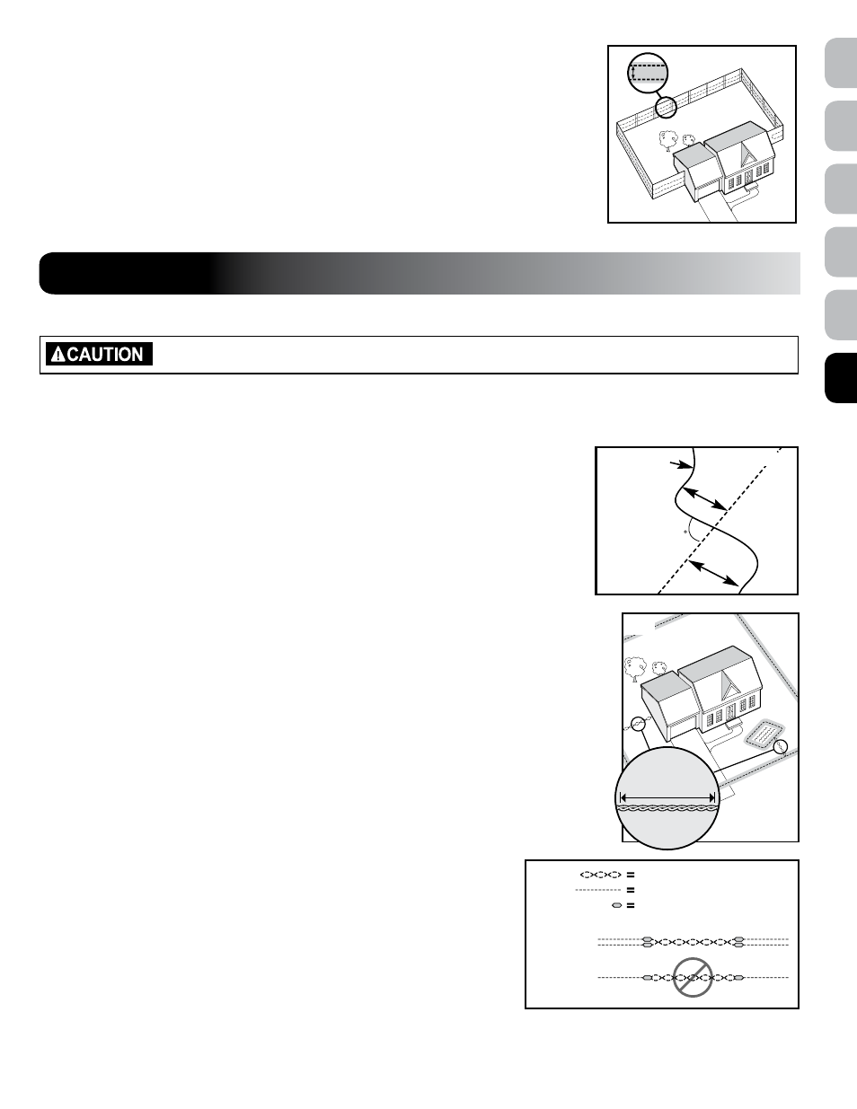
sample 6 (2i): Wire loop attached to existing Fence (Double loop)
This layout allows you to include your existing fence as part of your layout and keep your pet from
jumping out or digging under your existing fence. It reduces the amount of wire which will need to be
buried. Run the wire from the Fence Transmitter to
a, a to B, B to C, C to D, D to e, e to F, make a
U-turn and follow your path all the way back to
a, keeping the wire separated 1.5 m. Twist the wire
from
a back to the Fence Transmitter. See the “Install the Boundary Wire” section for more information
on attaching the wire to a fence.
E
F
B
A
D
C
1.5 m
2i
sTeP 3
Position the Boundary Wire
Risk of injury. Wire on top of the ground may be a trip hazard. Use care in how you place your wires.
lay out the Boundary Wire using your planned boundary and test the system BeFORe burying the wire or attaching it to an
existing fence. This will make any layout changes easier. Work carefully. a nick in the wire insulation can diminish the signal
strength and create a weak area where your pet can escape.
Running the Boundary Wire parallel to and within 3 m of electrical wires, neighbouring containment systems,
telephone wires, television or antenna cables, or satellite dishes may cause an inconsistent signal. If you must
cross any of these, do so at 90-degree angles (perpendicularly).
(3a)
If separating the wire by at least 3 m from a neighbouring containment system’s wire does not reduce the
inconsistent signal, contact the Customer Care Centre.
To Twist the Boundary Wire
Twisting the Boundary Wire cancels the signal and allows your pet to cross over that area without receiving
a stimulation
(3B). To ensure the signal is cancelled, it is recommended that you cut and splice the Boundary
Wire between each twisted section. The signal cannot be cancelled by running the wire through plastic or
metal piping. Splicing shielded cable to the Boundary Wire will also not cancel the signal. Refer to figure
(3C)
for the correct method for twisting the wire. You can twist your own wire by cutting two equal lengths of Boundary
Wire supplied and twisting them together. Anchor one end of the wires to something secure and insert the other
end in a power drill. Pull the wire taut. The drill enables you to twist the wire quickly. Twist the Boundary Wire 30
times per metre to cancel the signal. Once you have completed your boundary layout, insert the twisted wire into
the transmitter.
To splice or Repair the Boundary Wire
If you need additional Boundary Wire to expand your wire loop, you will need to splice the wires together. Note
the locations of all splices for future reference. Most Boundary Wire breaks occur at splices.
Strip approximately 1 cm of insulation off the ends of the Boundary Wires to be spliced
(3D). Make sure the
copper Boundary Wire is not corroded. If the Boundary Wire is corroded, cut it back to expose clean copper wire.
Insert the stripped ends into the wire nut and twist the wire nut around the wires. Ensure that there is no copper
exposed beyond the end of the wire nut. Tie a knot 7.5 cm - 10 cm from the wire nut
(3e). Ensure that the wire nut
is secure on the wire splice.
Once you have securely spliced the wires together, open the lid of the gel-filled splice capsule
and insert the wire nut as deeply as possible into the waterproof gel inside the capsule
(3F).
Snap the lid of the capsule shut
(3G). For proper system performance, the splice connection
must be waterproof.
If your splice pulls loose, the entire system will fail. Make sure your splice is secure. Additional
gel-filled splice capsules and wire nuts are available through the Customer Care Centre.
90
Boundary Wire
Bu
rie
d C
ab
le
3 m
3 m
3a
30 Twists/m
3B
TWISTED WIRES
BOUNDARY WIRE
WATERPROOF SPLICE
CORRECT
INCORRECT
3C
www.petsafe.net
139
EN
NO
RU
SV
DA
FI