Ab c – Инструкция по эксплуатации TIMBERK ICE.BEE series AC TIM 09HE P4
Страница 4
4
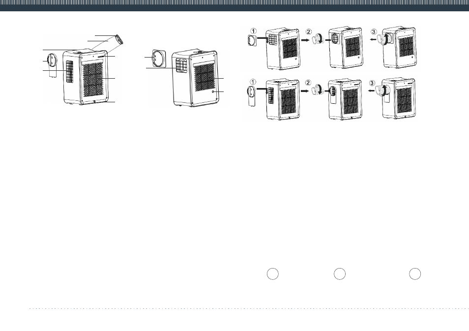
4. DEVICE DESCRIPTION (Fig. 3 and 4)
1. Control panel
2. Air-outlet
3. Removable grille
4. Nozzle
5. Air duct
6. Air inlet grille
7. Condensation drain hole
8. Place for remote control
9. Adapter of air duct
10. Air outlet
11. Condensation drain hole
12. Air inlet grille
Installation of air outlet hose (Fig. 5)
1. Prior to operation of the unit take off the removable cover and get the air
outlet hose, then insert it in the hole.
2. Rotate the air outlet hose in the direction, indicated by arrow 2 and take it
out from the removable grill.
3. Rotate the air outlet hose in the direction, indicated by arrow 3 and
connect it to the removable grill.
Installation of the hose in cooling / heating modes (Fig. 6)
To switch the air conditioner to heating it is necessary to install the hose to
the side, where cold air is coming out. To switch the air conditioner to
cooling it is necessary to install the hose to the side, where warm air is
coming out.
To switch the unit to the required mode (cooling/heating):
Disconnect the removable grill and the air outlet hose, as shown by the
arrow in Fig. 6 A, then interchange their position (B) and connect to the
unit. Final structure is shown in Fig.6 C.
www.timberk.com electric floor standing air onditioner ortable type (single case)
Fig. 6
Fig. 5
Fig. 3
Fig. 4
(9)
(10)
(12)
(11)
(1)
(3)
(2)
(4)
(5)
(8)
(6)
(7)
A
B
C