Cyborg start, Wiring description, Схема подключений – Инструкция по эксплуатации Mongoose Cyborg Start
Страница 11
Installation Manual
CYBORG START
6
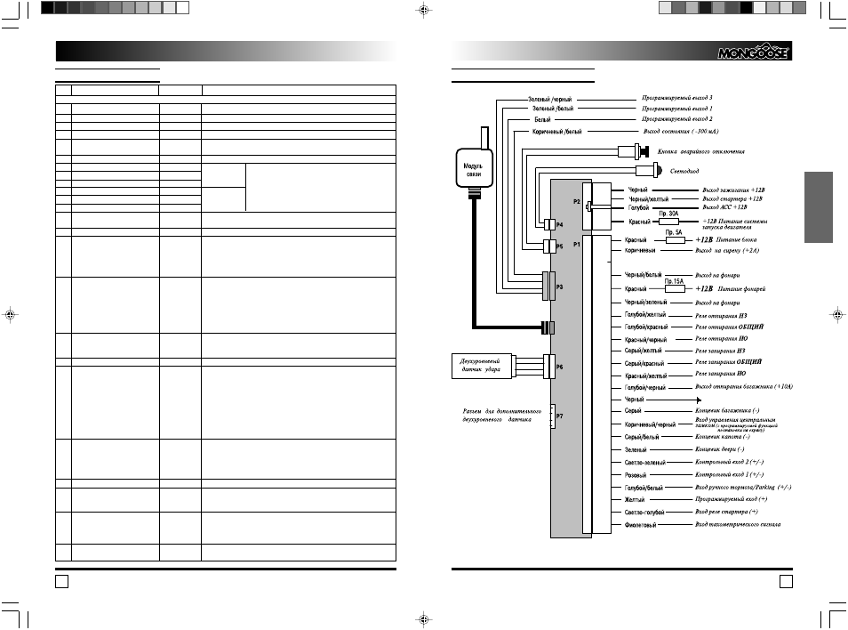
Wiring Description
1
Main Unit Power Supply
Red
Connect to +12V contact of the car battery via 5A fuse.
2
Siren Output
Brown
+ 2 A
3
Not used
4
Indicators Output
Black/White
Built in Relay Contact.
Connect to the right side indicators feed wire.
5
Indicators Polarity
Red
Connect to +12V contact of the car battery via 15A fuse. (In case of negative
polarity of the Indicator control wire connect to the car body via 15A fuse).
6
Indicators Output
Black/Green
Built in Relay Contact.
Connect to the left side indicators feed wire.
7
Unlock Normally Closed Contact
Blue/Yellow
8
Unlock Common Contact
Blue/Red
Built in Relay
See Central Door Lock Connection Diagrams
9
Unlock Normally Opened Contact
Red/Black
10
Lock Normally Closed Contact
Grey/Yellow
11
Lock Common Contact
Grey/Red
Built in Relay
12
Lock Normally Opened Contact
Red/Yellow
13
Power Trunk Release Output +10A
Blue/Black
Connect to the positive trunk release line. Install a trunk release actuator if there
is no OE actuator.
14
Ground “ ”
Black
Connect to the car body.
15
Negative Trunk Trigger Input
Grey
While remote trunk opening in armed stage the input will be overridden
until 10 seconds of trunk is closed.
The trunk pin switch should be mounted onto the car body metal. Make sure the
switch is reliable disconnected when the trunk cowl is closed, and will be
grounded as soon as the trunk is opened.
16
Negative Central Door Lock Control Brown/Black
Connect to the master actuator output, which is grounded in “open” position and
Input One of two options can be
stays free in “closed” position.
selected for this input with the
Installer Function 3 4.
1. CDL Control Input.
2. CDL Control Input with arming
on locking.
17
Negative Hood Trigger input
Grey/White
The hood pin switch should be mounted onto the car body metal. Make sure the
switch is reliable disconnected when the hood is closed, and will be grounded as
soon as the hood is opened.
18
Negative Door Trigger Input
Green
The input has the “Dome Light Cars” selectable option.
(Installer function 1 2).
19
Programmable Control Input 2
Light Green
The input can be adjusted to operate as:
*
The mode of the input operation is
1. Low Fuel Warning. Connect to the Low Fuel Control Lamp.
set by the Installer’s function 1 5.
As soon as the lamp is switched on all remote and automatic start operation
Polarity of the input operation is set
will be forbidden by the system. The LCD will display the Low Fuel Indicator until
by the Installer’s function 1 6.
the first switching the ignition on with normal fuel level.
2. Glow Plug Monitor. Connect to the Glow Plug wire. The system will monitor
the glow plug status and will crank the engine as soon as glow plug is switched
off, but not later than in 1 minute. This mode is only available when
the Installer’s function 2 5 set to Diesel Mode.
20
Programmable Control Input 1
Pink
The input can be adjusted to operate as:
*
The mode of the input operation is
1. Overheating Protection. If a vehicle includes an Overheating Control Lamp,
set by the Installer’s function 1 3.
connect to this lamp.
Polarity of the input operation is set
2. Generator/Oil Lamp Monitor. Connect to Generator or Oil lamp if
by the Installer’s function 1 4.
generator/oil lamp monitoring of engine running/started is selected with programming.
21
Handbrake Input
Blue/White
Connect to the handbrake switch.
22
Positive Programmable Input
Yellow
1. Positive Door Trigger Input.
The mode of the input operation is
2. Shining Light Warning. (Connect to the Parking Lights Feed Wire).
set by the Installer function 1 1.
23
Starter Input (+)
Light Blue
Cut the starter wire on the ignition key and connect the light blue wire to the key
side of the starter wire. Connect the Black/yellow starter power output wire to
the motor side of the starter wire. Such connection will allow both blocking the
starter when armed and anti grinding protection after remote or automatic start.
24
RPM Control Input
Purple
If RPM monitoring of engine running/started is selected connect the RPM
signal circuit. Fulfill the RPM Leaning in the Installer’s function 2 7.
N
Wire Destination
Wire Color
Note
24 pin Connector
Автомобильная охранная система “MONGOOSE” Модель CYBORG START
23
РУССКИЙ
СХЕМА ПОДКЛЮЧЕНИЙ