Cyborg start, Проверка системы, Настройка датчиков – Инструкция по эксплуатации Mongoose Cyborg Start
Страница 10
Two Way Car Alarm System MONGOOSE CYBORG START
7
ENGLISH
N
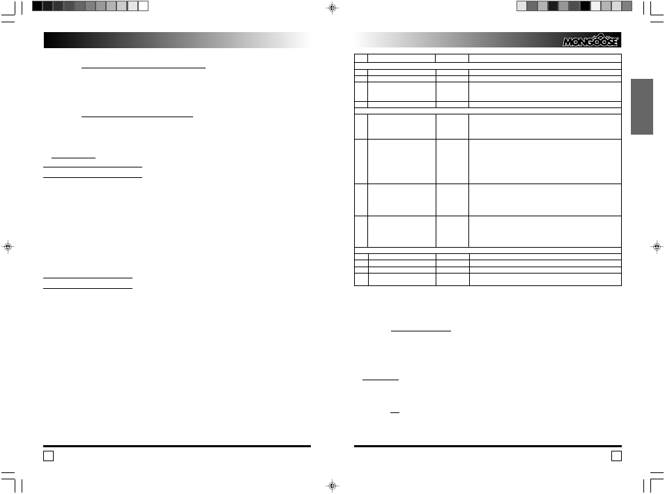
Wire Destination
Wire Color
Note
Power 4 pin Connector of the Remote Start System
1
Ignition +12V
Black
Connect to the Ignition wire at the ignition key cylinder.
2
Starter Output +12V
Black/Yellow
Connect to the starter relay control line.
3
ACC Output +12V
Blue
Connect to the ACC wire at the ignition key cylinder.
The installer’s function 4 4 set the
Depending on program setting the output can be switched on in
delay of activation the output.
either 1 minute or 2 seconds after the engine is started up.
4
Remote Start System Power Supply Red
Connect to +12V contact of the car battery via 30A fuse.
4 pin Low Current Connector (Red Color)
1
Arm Output (programmable).
Brown/White
1. “ ”300 mA when Armed.
To control an extra normally closed blocking relay.
The mode operation of the Arm
2. “ ”300 mA when Disarmed.
To control an extra normally opened blocking relay.
Output you select with Installer’s
function 4 1.
2
Programmable Output 2 “ ”300 mA White
Depending on the program setting the output can operate as:
The mode of the output operation is
1. Latch Output. The output will be switched on regardless of the ignition is
set by the Installer function 4 3.
switched on or off and alarm system is armed or disarmed when buttons 3 and 4
are pressed at the same time. The second press of buttons 3 and 4 or disarming
will switch off the output.
2. Brake/Clutch Output for the cars require the brake or clutch pedal to be
depressed to allow cranking the engine.
3
Programmable Output 1 “ ”300 mA Green/White
You can select one of three options for the output:
The mode of the output operation is
1. 20 secon Comfort Window Close on Arming.
set by the Installer function 4 2.
(Connect to the coil of the window closing relay).
2. ACC 2.
3. Two stage Unlock. (Connect to the coil of passengers’ door unlocking relay).
4
Programmable Output 3 “ ”300 mA White
You can select one of three options for the output:
The mode of the output operation is
1. Ignition 2 Output.
set by the Installer function 4 5.
2. OE Alarm Disarm Output 1. 2 second pulse before the first cranking.
3. OE Alarm Disarm Output 2. Permanently fed until the ignition support is
switched off.
Other Connections
LED Output
2 pin White Connector
Override Switch Input
2 pin White Connector
RF Base Station Input/Output
4 pin Blue Connector
Shock Senor and Optional Sensor
Two 4 pin White Connectors
Inputs
* Programmable Control Inputs 1 and 2 operation
Control Input 1 (Pink Wire)
Function: Temperature Warning
If positive polarity has been selected the Input detects the engine overheating (switching of
the control lamp) when signal polarity changes from “+” to “ ”, and if negative polarity has
been selected the Input detects the engine overheating when signal polarity changes from “ ”
to “+”. The Input starts monitoring of the overheating lamp in 1 minute after remote (automatic)
engine start. As soon as the polarity has changed the system will stop the engine.
WARNING! The Control Input 1 includes a pull low resistor inside the electronic module, so
if positive polarity is selected for the Temperature Warning (Default Setting) and the Input is not
used, it is necessary to connect the pink wire to permanent “+” or change polarity to negative,
as otherwise the system will switch off the engine in 1 minute after the engine has been started.
Function: Oil
If positive polarity has been selected the Input detects the engine has started when signal
polarity has changed from “ ” to “+” and if negative polarity has been selected the Input
detects the engine has started when signal polarity has changed from “+” to “ ”.
Инструкция по установке
CYBORG START
22
Проверка системы
1. Подсоединить аккумулятор автомобиля.
2. Проверить следующие устройства и режимы:
постановка/снятие с охраны;
тихая постановка/снятие с охраны;
паника;
срабатывание датчика удара и дополнительного датчика;
двушаговое снятие с охраны»
срабатывание при открывании всех дверей, капота, багажника;
отсутствие срабатывания концевиков капота/багажника при колебании крышек
капота/багажника;
работа кнопки аварийного отключения;
управление центральным замком;
управление дополнительными каналами (если подключены);
автопостановка, перепостановка (защита от случайного снятия с охраны);
Valet режим;
Радиус действия пультов управления;
Блокировка двигателя;
Работу системы управления запуском двигателя.
Настройка датчиков.
При настройке датчика удара и, если установлен, дополнительного датчика устано
вите регуляторы чувствительности в среднее положение. Проверьте чувствительность
датчика удара, постукивая рукой по кузову автомобиля. Чувствительность объемного
датчика проверяется движением руки в салоне через приоткрытое окно для однозонного
датчика или основной зоны двузонного датчика; чувствительность предупредительной
зоны проверяется движением вблизи автомобиля.
При необходимости увеличить чувствительность датчика поверните регулятор по
часовой стрелке, для уменьшения чувствительности – против часовой стрелки.
Помните, что избыточная чувствительность может привести к большому числу лож
ных срабатываний системы.
Контрольный вход 2 (Светло зеленый провод):
Функция: Предупреждение о низком уровне топлива
При выборе положительной полярности вход фиксирует низкий уровень топлива (вклю
чение контрольной лампы) при смене полярности сигнала с “ ” на “+” а при выборе
отрицательной с “+” на “ ”.
Вход отслеживает состояние сигнальной лампы уровня топлива только при включен
ном зажигании
Функция: Контрольный вход свечи накаливания
При выборе положительной полярности вход разрешает запуск двигателя при смене
полярности сигнала с “ ” на “+” а при выборе отрицательной с “+” на “ ”.
Вход работает только при программном включении функцией 2 5 Дизельного режи
ма.
ВНИМАНИЕ! Контрольный вход 2 имеет внутреннюю привязку к “ ”.