Installation/connection – Инструкция по эксплуатации Hyundai H-CMD7080
Страница 7
7
Installation/Connection
Connection
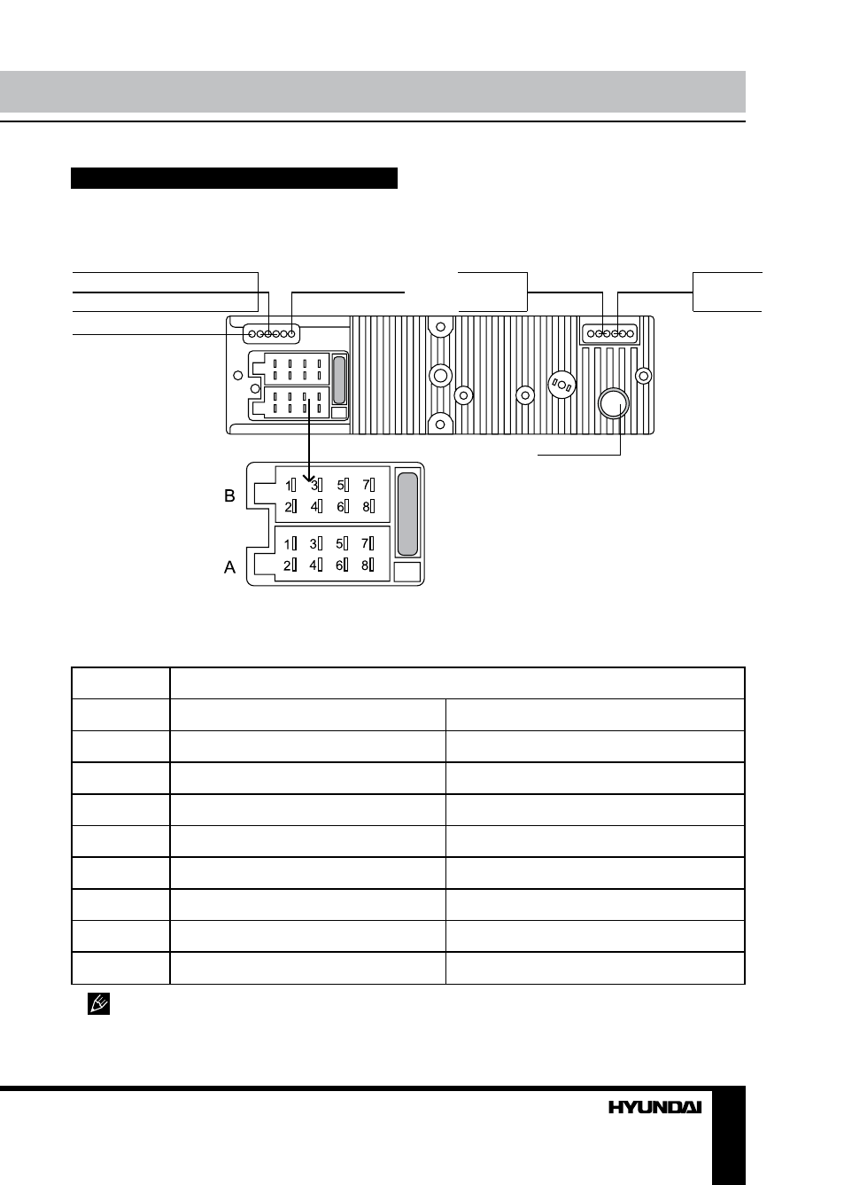
Connection diagram
Connector A
1. -
2. -
3. -
4. Memory +12V
5. Auto antenna output
6. To dimmer control
7. +12V (to ignition key)
8. Ground
Connector B
1. Rear right speaker (+)
2. Rear right speaker (-)
3. Front right speaker (+)
4. Front right speaker (-)
5. Front left speaker (+)
6. Front left speaker (-)
7. Rear left speaker (+)
8. Rear left speaker (-)
ISO connector
DVD video RCA out (yellow)
Red-Right
Red-Right
Line out
Grey-Front
Line out
Brown-Rear
DVD audio RCA out (white-left)
DVD audio RCA out (red-right)
White-Left
White-Left
Parking (brown)
Subwoofer out (blue)
Antenna jack
ISO connection table
Location
1
2
3
4
5
6
7
8
Connector A
Battery 12V (+)/yellow
Power Antenna/Blue
Dimmer/Orange
ACC+/Red
Ground/Black
Connector B
Rear Right(+)---Violet
Rear Right(-)---Violet/Black Stripe
Front Right(+)---Grey
Front Right(-)---Grey/Black Stripe
Front Left(+)---White
Front Left((-)---White/Black Stripe
Rear Left(+)---Green
Rear Left(-)---Green/Black Stripe
Function
Power antenna wire is intended for power supply of the antenna and for remote control of
an additional amplifier.