Sp-p/o mode (rear output and preout set, System menu, Using an aux source – Инструкция по эксплуатации Pioneer MVH-X460UI
Страница 11: If an unwanted display appears, Connections, Using this unit, Installation
Black plate (11,1)
SP-P/O MODE (rear output and preout setting)
The rear speaker leads output and the RCA output
of this unit can be used to connect a full-range
speaker or subwoofer. Select a suitable option for
your connection.
1 Press M.C. to display the setting mode.
2 Turn M.C. to select the desired setting.
! REAR/SUB.W – Select when there is a full-
range speaker connected to the rear speak-
er leads output and there is a subwoofer
connected to the RCA output.
! SUB.W/SUB.W – Select when there is a
subwoofer connected directly to the rear
speaker leads output without any auxiliary
amp and there is a subwoofer connected
to the RCA output.
! REAR/REAR – Select when there is a full-
range speaker connected to the rear speak-
er leads output and the RCA output.
If there is a full-range speaker connected to
the rear speaker leads output and the RCA
output is not used, you may select either
REAR/SUB.W or REAR/REAR.
System menu
1
Press and hold SRC/OFF until the unit
turns off.
2
Press and hold SRC/OFF until the main
menu appears in the display.
3
Turn M.C. to change the menu option
and press to select SYSTEM.
4
Turn M.C. to select the system menu
function.
For details, refer to System menu on page 9.
Using an AUX source
1
Use the AUX cable to connect an auxiliary
device to this unit.
2
Press SRC/OFF to select AUX as the
source.
Note
AUX cannot be selected unless the auxiliary set-
ting is turned on. For more details, refer to
Switching the display
Selecting the desired text information
1 Press DISP to cycle between the following:
! Source name
! Source name and clock
If an unwanted display appears
Turn off the unwanted display using the proce-
dures listed below.
1
Press M.C. to display the main menu.
2
Turn M.C. to change the menu option
and press to select SYSTEM.
3
Turn M.C. to display DEMO OFF and press
to select.
4
Turn M.C. to switch to YES.
5
Press M.C. to select.
Connections
Important
! When installing this unit in a vehicle without
an ACC (accessory) position on the ignition
switch, failure to connect the red cable to the
terminal that detects operation of the ignition
key may result in battery drain.
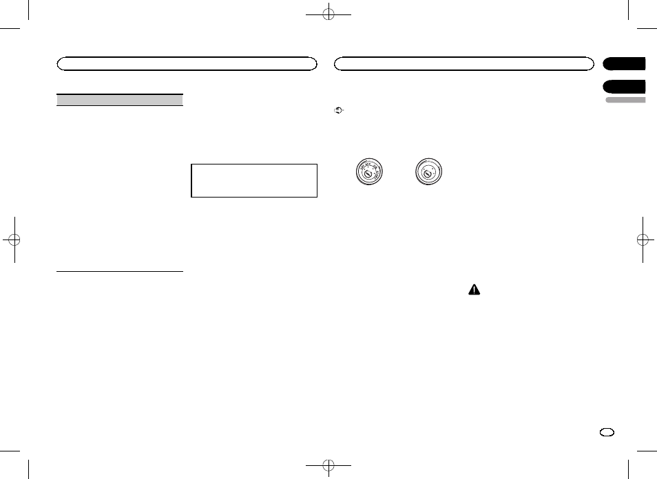
ON
S
T
A
R
T
O
FF
ACC position
No ACC position
! Use of this unit in conditions other than the
following could result in fire or malfunction.
— Vehicles with a 12-volt battery and negative
grounding.
— Speakers with 50 W (output value) and 4 W to
8
W (impedance value).
! To prevent a short-circuit, overheating or mal-
function, be sure to follow the directions
below.
— Disconnect the negative terminal of the bat-
tery before installation.
— Secure the wiring with cable clamps or adhe-
sive tape. Wrap adhesive tape around wiring
that comes into contact with metal parts to
protect the wiring.
— Place all cables away from moving parts,
such as the shift lever and seat rails.
— Place all cables away from hot places, such
as near the heater outlet.
— Do not connect the yellow cable to the battery
by passing it through the hole to the engine
compartment.
— Cover any disconnected cable connectors
with insulating tape.
— Do not shorten any cables.
— Never cut the insulation of the power cable of
this unit in order to share the power with
other devices. The current capacity of the
cable is limited.
— Use a fuse of the rating prescribed.
— Never wire the negative speaker cable directly
to ground.
— Never band together negative cables of multi-
ple speakers.
! When this unit is on, control signals are sent
through the blue/white cable. Connect this
cable to the system remote control of an ex-
ternal power amp or the vehicle
’s auto-anten-
na relay control terminal (max. 300 mA
12 V DC). If the vehicle is equipped with a
glass antenna, connect it to the antenna
booster power supply terminal.
! Never connect the blue/white cable to the
power terminal of an external power amp.
Also, never connect it to the power terminal
of the auto antenna. Doing so may result in
battery drain or a malfunction.
! The black cable is ground. Ground cables for
this unit and other equipment (especially,
high-current products such as power amps)
must be wired separately. If they are not, an
accidental detachment may result in a fire or
malfunction.
This unit
CAUTION
Use a USB cable when connecting a USB stor-
age device. Connecting a USB storage device di-
rectly may be dangerous because it may stick
out.
! To use the USB port to connect a device, pre-
pare and use a USB cable sold separately.
! To use the AUX input jack to connect a de-
vice, prepare and use the AUX cable sold
separately.
English
Using this unit
11
Section
Installation
En
02
03
<QRD3244-A>11