Router eng – Инструкция по эксплуатации WORX Tools WU601.1
Страница 11
Router ENG
• When vacuuming dry dust that is especially
detrimental to health or carcinogenic, use a
special vacuum cleaner.
3. ON AND OFF SWITCH
For starting the machine, actuate the lock-off
button (16) first, and then press and hold the
On/Off switch (18) afterwards.
Speed Pre-selection
The required speed can be pre-selected with
the thumb-wheel (17) (also whilst running).
1 – 2 = low speed
3 – 4 = medium speed
5 – 6 = high speed
The required speed is dependent on the material
and can be determined by practical testing.
After longer periods of working at low speed,
allow the machine to cool down by running it
for approx. 3 minutes at maximum speed with
no load.
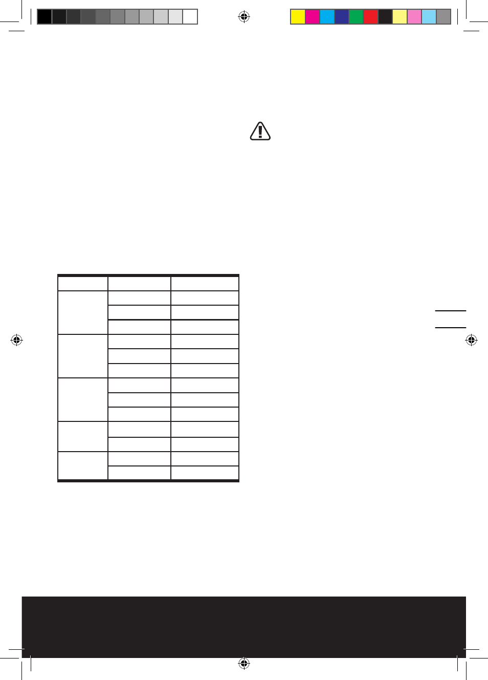
Speed Table
Material
Router bit-Ø Speed stages
Hardwood
(Beech)
4 – 10mm
5-6
12 – 20mm
3-4
22 – 40mm
1-2
Softwood
(Pine)
4 – 10mm
5-6
12 – 20mm
3-6
22 – 40mm
1-3
Particle
board
4 – 10mm
3-6
12 – 20mm
2-4
22 – 40mm
1-3
Plastic
4 – 15mm
2-3
16 – 40mm
1-2
Aluminum
4 – 15mm
1-2
16 – 40mm
1
The values shown in the chart are standard
values. The necessary speed depends on the
material and the operating conditions, and can
be determined by practical testing.
Constant Electronic Control and Soft Start
(Only for WU601&WU601.1)
Constant electronic control maintains the speed
constant at no-load and under most working
conditions. Soft start delays the increase in
motor speed to reduce the motor “kick” or
torque effect to improve operator comfort and
safety.
4. SETTING THE DEPTH-OF-CUT
Depending on the cutting operation, the depth
of cut can be preset in several steps.
The adjustment of the depth-of-cut
may only be carried out when the
router is switched off.
Coarse Adjustment of the Depth-of-cut
Place the router on the work-piece to be
machined.
Set the fine adjustment for depth-of-cut in the
center position with fine-adjustment knob (1);
to do this, turn the fine-adjustment knob until
the markings (23) on the backside of the router
are in alignment, as shown. Afterwards turn
scale (2) to “0” (See C). Set step buffer (9) to the
lowest position; the buffer snaps-in noticeably.
Loosen locking screw (7), so that depth stop (6)
can be moved freely.
Release the clamping lever (3) by turning in
clockwise direction and slowly lower the router
until the router bit touches the surface of the
workpiece. Lock the router in position by turning
the clamping lever in anti-clockwise direction.
Press depth stop downwards until it touches
the stop buffer (9). Adjust the depth stop (6) to
the required routing depth and tighten the wing
screw (7). Release the clamping lever and guide
the router back up again.
The coarse adjustment of the depth-of-cut
should be checked by a trial cut and corrected,
if necessary.
Fine Adjustment of the Depth-of-cut
After a trial cut, fine adjustment can be carried
out by turning the fine adjustment knob (1
scale mark = 0.1 mm/1 rotation = 2.0
mm). The maximum adjustment is approx.
+/– 8 mm.
Example: Slide router upwards again and
measure the depth-of-cut (set value = 10.0 mm;
actual value = 9.8 mm).
Lift up router and underlay guide plate (11) in
such a manner that the router can plunge freely
without the router bit touching the work-piece.
Lower the router again until the depth stop
touches the step buffer (9).
Afterwards set scale (2) to “0”.
Loosen wing screw.
With the fine adjustment (1), advance the depth-
of-cut in clockwise direction by 0.2 mm/
2 scale marks (= difference between required
11
10
UKR-WU600 WU600.1 WU601 WU601.1-M-060726.indd 11
2006-7-26 14:08:54