Инструкция по эксплуатации Saturn ST-CC0229
Страница 3
4
could cause a risk of fire, electric
shock or injury to persons, when the
appliance is used.
11. Indoor use only.
12. The appliance only can be
connected with sockets with earth
wire.
13. Water should be put into water
tank before setting power.
14. Burns could occur from touching
hot parts, hot water or steam use cars
when you empty a steam appliance
there may be hot water in the
reservoir.
15. After using, wait for unit natural
cooling.
16. After using, pull out the power
plug from socket.
17. Do not pull out steam pipe during
use.
18. The power plug shall be pulled out
from socket, when filling water and
cleaning.
19. There’s no heating device in the
steam spray board. So do not take the
brush down during using.
20. This appliance is not intended for
use by persons (including children)
with reduced physical, sensory or
mental
capabilities,
or
lack
of
experience and knowledge, unless
they have been given supervision or
instruction concerning use of the
appliance by a person responsible for
their safety.
21. Children should be supervised to
ensure that they do not play with the
appliance.
22. Don’t put the appliance on the
desk or chair. The appliance only can
be put on the ground.
23. Be careful of the hot little water
coming out from the brush before
using.
24. Do not pull out the steam pipe
during use.
25. Do not let the water flow into the
body from water outlet in order to
avoid damaging the inner parts.
26. Do not remove the water tank,
when humidifier working.
WARNING:
Do not clean the appliance under tap
water.
Be careful of the hot steam from
steam pipe.
Do not bend the brush head.
Do not pull out the power cord from
outlet by wet hand.
Steamer Parts Diagram
DRA
WIN
G
NO.
NAME OF
PARTS
1
Fixed sheath for
rod-set
2
Fixed knob for
rod-set
3
Panel
4
Fixed rack for
copper tube
5
Fixed shelves for
copper tube
6
Indicator
7
Power switch
8
Indicator
9
Upper of body
10
Bottom of body
11
Water drain pipe
nut
12
Water inlet pipe
13
Increase weight
14
Water tank
15
Water
tank
cover
16
360° truckle
17
Wheel
5
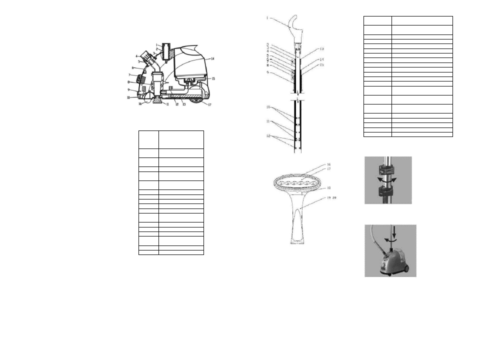
DRAW-
ING NO.
NAME OF PARTS
1
Against
slide
hose
hanger
2
Highest section of rod
3
Fixed sets of upper rod
4
Lock button
5
Upper section of rod
6
Fixed sets of middle rod
7
Middle section of rod
8
Lower section of rod
9
Bracket
10
Antiskid of top rod
11
Antiskid of upper rod
12
Antiskid of middle rod
13
Antiskid lining of upper
rod
14
Antiskid lining of middle
rod
15
Antiskid lining of lower
rod
16
Brush
17
Al-plate of brush
18
Brush head
19
Top cover of brush
20
Bottom cover of brush
Installation & Operation
1. Take out rod set and against slide
hose hanger. Install the hanger.
2. Cut rod-set in Fixed Sheath of Rod-
set. Screw the knob for fixing rod.