Выбор режима кодера, Selecting encoder modes – Инструкция по эксплуатации Yamaha dm2000v2e1
Страница 61
DM2000 Version 2—Owner’s Manual
61
Основы управления микшером
Выбор режима кодера
Функция кодеров зависит от выбранного уровня и режима кодера. Имеется
2 стандартных режима кодера – Pan и Aux/Mtrx и 4 режима, настраиваемых
пользователем, в которых можно задать более 40 параметров.
1 Выберите необходимый уровень (см. стр. 58).
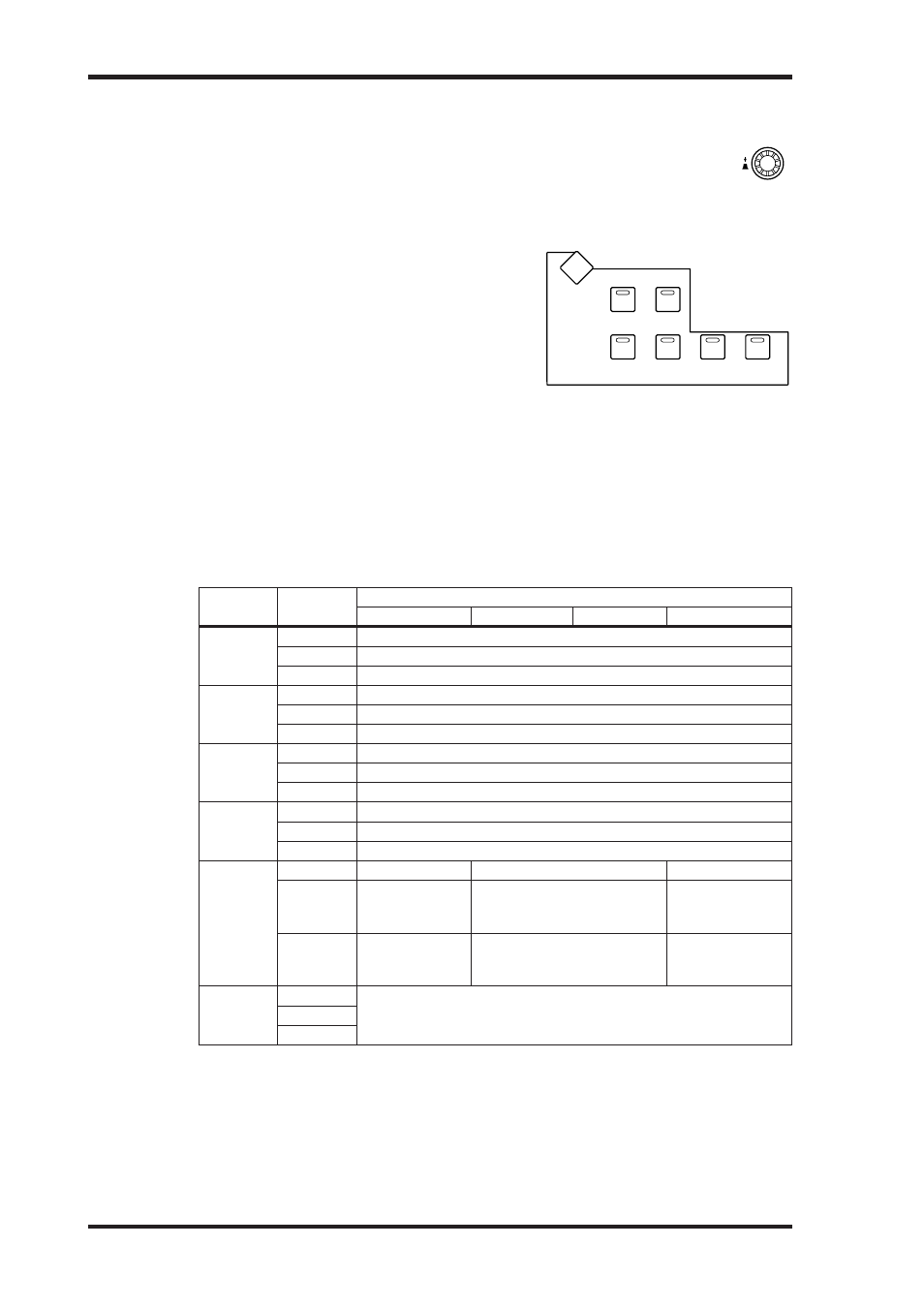
2 Нажмите соответствующую кнопку ENCODER
MODE для выбора режима кодера.
[PAN]: Кодеры используются в качестве регуля-
тора панорамы. При нажатии кнопки кодера на
полосах каналов появляется текущая позиция
панорамы.
[AUX/MTRX]: Кодеры используются для настрой-
ки уровня дополнительных посылов или посылов
Matrix – в зависимости от выбранного уровня. При
нажатии кнопки кодера на полосах каналов появляется текущий уровень дополнитель-
ных посылов или посылов Matrtix.
[ASSIGN 1-4]: Кодеры управляют параметрами, закрепленными за кнопками [ASSIGN].
Дополнительная информация о том, как назначить параметры для кнопкок [ASSIGN],
приведена на стр. 62.
Индикатор нажатой кнопки ENCODER MODE загорается.
В следующей таблице показаны функции кодера для каждого уровня и режима.
Уровень
Режим
кодера
Кодер
1-8
9-16
17-20
21-24
1-24
Pan
Панорама входных каналов 1-24
Aux/Mtrx
Уровень дополнительных посылов входных каналов 1-24
Assign 1-4
Назначенный параметр1 каналов 1-24
25-48
Pan
Панорама входных каналов 25-48
Aux/Mtrx
Уровень дополнительных посылов входных каналов 25-48
Assign 1-4
Назначенный параметр1 каналов 25-48
49-72
Pan
Панорама входных каналов 49-72
Aux/Mtrx
Уровень дополнительных посылов входных каналов 49-72
Assign 1-4
Назначенный параметр1 каналов 49-72
73-96
Pan
Панорама входных каналов 73-96
Aux/Mtrx
Уровень дополнительных посылов входных каналов 73-96
Assign 1-4
Назначенный параметр1 каналов 73-96
Ведущий
Pan
---
---
Matrix 1-4: баланс
Aux/Mtrx
Выходная шина
1-8: уровень по-
сыла Matrix
Дополнительный посыл 1-12:
уровень посыла Matrix
---
Assign 1-4
Выходная шина
1-8: назначен-
ный параметр
Дополнительный посыл 1-12:
назначенный параметр
Посыл Matrix 1-4:
назначенный па-
раметр
Удаленный
1-4
Pan
Действие зависит от выбранного назначения сигнала
(см. стр. 253).
Aux/Mtrx
Assign 1-4
1, если назначен параметр Alt Layer (альтернативный уровень), кодер управляет параметром, закрепленным
за соответствующим фейдером канала в «другом» уровне (т.е, если текущим является уровень каналов 1-24,
«другим» уровнем является уровень 25-48;, если текущим является уровень 49-72, «другим» уровнем является
уровень 73-96).
Значения параметров, управляемых кодерами, выводятся в графическом виде в окне
полос канала (см. также стр. 55).
Selecting Encoder Modes
61
DM2000 Version 2—Owner’s Manual
Selecting Encoder Modes
The exact function of each Encoder depends on the selected Layer and Encoder
mode. There are two preset Encoder modes, Pan and Aux/Mtrx, and four assign-
able modes, for which you can choose from over 40 parameters.
1
Select a Layer, as explained in page 58.
2
Use the ENCODER MODE buttons to select
an Encoder mode.
[PAN]: Encoders function as Pan controls. When
you press the Encoder push-switches, the current
Pan positions appear on the channel strip displays.
[AUX/MTRX]: Encoders control Aux or Matrix
Send levels, depending on the selected Layer. When
you press the Encoder push-switches, the currently-selected Aux or Matrix Send levels
appear on the channel strip displays.
[ASSIGN 1–4]: Encoders control the parameters assigned to the ASSIGN buttons. See
“Assigning Parameters to the ENCODER MODE Assign Buttons” on page 62 for more
information.
The indicator of the currently selected ENCODER MODE button lights up.
The following table shows the exact Encoder functions for each Layer and Encoder mode.
The values of the parameters being controlled by the Encoders are displayed graphically by
the channel strip displays. See “Channel Strip Displays” on page 55 for more information.
Layer
Encoder
Mode
Encoder
1–8
9–16
17–20
21–24
1–24
Pan
CH 1–24: pan
Aux/Mtrx
CH 1–24: Aux Send level
Assign 1–4
CH 1–24: assigned parameter
1
1. When Alt Layer is assigned, the Encoders enable you to control a parameter that is assigned to the cor-
responding channel fader in the partner layer. (A partner layer would be the layer of channels 25-48
if the layer of channels 1-24 is currently selected, or the layer of channels 73-96 if the layer of channels
49-72 is currently selected.)
25–48
Pan
CH 25–48: pan
Aux/Mtrx
CH 25–48: Aux Send level
Assign 1–4
CH 25–48: assigned parameter
1
49–72
Pan
CH 49–72: pan
Aux/Mtrx
CH 49–72: Aux Send level
Assign 1–4
CH 49–72: assigned parameter
1
73–96
Pan
CH 73–96 pan
Aux/Mtrx
CH 73–96: Aux Send level
Assign 1–4
CH 73–96: assigned parameter
1
Master
Pan
No operation
No operation
Matrix 1–4: Balance
Aux/Mtrx
Bus Out 1–8:
Matrix Send level
Aux Send 1–12:
Matrix Send level
No operation
Assign 1–4
Bus Out 1–8:
assigned parameter
Aux Send 1–12:
assigned parameter
Matrix Send 1–4:
assigned parameter
Remote
1–4
Pan
Operation depends on the selected target.
See “About Remote Layers” on page 253 for more information.
Aux/Mtrx
Assign 1–4
AUX/ MTRX
PAN
ASSIGN
4
ASSIGN
3
DISPLAY
ASSIGN
2
ASSIGN
1
PAN
SEND LEVEL
INSERT
SEND ASSIGN
OUTPUT
INPUT
ENCODER MODE
Selecting Encoder Modes
61
DM2000 Version 2—Owner’s Manual
Selecting Encoder Modes
The exact function of each Encoder depends on the selected Layer and Encoder
mode. There are two preset Encoder modes, Pan and Aux/Mtrx, and four assign-
able modes, for which you can choose from over 40 parameters.
1
Select a Layer, as explained in page 58.
2
Use the ENCODER MODE buttons to select
an Encoder mode.
[PAN]: Encoders function as Pan controls. When
you press the Encoder push-switches, the current
Pan positions appear on the channel strip displays.
[AUX/MTRX]: Encoders control Aux or Matrix
Send levels, depending on the selected Layer. When
you press the Encoder push-switches, the currently-selected Aux or Matrix Send levels
appear on the channel strip displays.
[ASSIGN 1–4]: Encoders control the parameters assigned to the ASSIGN buttons. See
“Assigning Parameters to the ENCODER MODE Assign Buttons” on page 62 for more
information.
The indicator of the currently selected ENCODER MODE button lights up.
The following table shows the exact Encoder functions for each Layer and Encoder mode.
The values of the parameters being controlled by the Encoders are displayed graphically by
the channel strip displays. See “Channel Strip Displays” on page 55 for more information.
Layer
Encoder
Mode
Encoder
1–8
9–16
17–20
21–24
1–24
Pan
CH 1–24: pan
Aux/Mtrx
CH 1–24: Aux Send level
Assign 1–4
CH 1–24: assigned parameter
1
1. When Alt Layer is assigned, the Encoders enable you to control a parameter that is assigned to the cor-
responding channel fader in the partner layer. (A partner layer would be the layer of channels 25-48
if the layer of channels 1-24 is currently selected, or the layer of channels 73-96 if the layer of channels
49-72 is currently selected.)
25–48
Pan
CH 25–48: pan
Aux/Mtrx
CH 25–48: Aux Send level
Assign 1–4
CH 25–48: assigned parameter
1
49–72
Pan
CH 49–72: pan
Aux/Mtrx
CH 49–72: Aux Send level
Assign 1–4
CH 49–72: assigned parameter
1
73–96
Pan
CH 73–96 pan
Aux/Mtrx
CH 73–96: Aux Send level
Assign 1–4
CH 73–96: assigned parameter
1
Master
Pan
No operation
No operation
Matrix 1–4: Balance
Aux/Mtrx
Bus Out 1–8:
Matrix Send level
Aux Send 1–12:
Matrix Send level
No operation
Assign 1–4
Bus Out 1–8:
assigned parameter
Aux Send 1–12:
assigned parameter
Matrix Send 1–4:
assigned parameter
Remote
1–4
Pan
Operation depends on the selected target.
See “About Remote Layers” on page 253 for more information.
Aux/Mtrx
Assign 1–4
AUX/ MTRX
PAN
ASSIGN
4
ASSIGN
3
DISPLAY
ASSIGN
2
ASSIGN
1
PAN
SEND LEVEL
INSERT
SEND ASSIGN
OUTPUT
INPUT
ENCODER MODE