Connecting the units <english – Инструкция по эксплуатации Pioneer DEH-1310
Страница 2
Внимание! Текст в этом документе был распознан автоматически. Для просмотра оригинальной страницы Вы можете воспользоваться режимом "Оригинал".
Connecting the Units
<ENGLISH>
Note:
•
This unit is for vehicles with a 12-volt battery and
negative grounding. Before installing it in a recre
ational vehicle, truck, or bus, check the battery
voltage.
•
To avoid shorts in the electrical system, be sure to
disconnect the © battery cable before beginning
installation.
•
Refer to the owner’s manual for details on con
necting the power amp and other units, then make
connections correctly.
•
Secure the wiring with cable clamps or adhesive
tape. To protect the wiring, wrap adhesive tape
around them where they lie against metal parts.
•
Route and secure all wiring so it cannot touch any
moving parts, such as the gear shift, handbrake
and seat rails. Do not route wiring in places that
get hot, such as near the heater outlet. If the insu
lation of the wiring melts or gets tom, there is a
danger of the wiring short-circuiting to the vehicle
body.
•
Don’t pass the yellow lead through a hole into the
engine compartment to connect to the battery.
This will damage the lead insulation and cause a
very dangerous short.
•
Do not shorten any leads. If you do, the protection
circuit may fail to work when it should.
•
Never feed power to other equipment by cutting
the insulation of the power supply lead of the unit
and tapping into the lead. The current capacity of
the lead will be exceeded, causing overheating.
•
When replacing fuse, be sure to use only fuse of
the rating prescribed on this unit.
•
Since a unique BPTL circuit is employed, never
wire so the speaker leads are directly grounded or
the left and right 0 speaker leads are common.
•
The black lead is ground. Please ground this lead
separately from the ground of high-current prod
ucts such as power amps.
If you ground the products together and the
ground becomes detached, there is a risk of dam
age to the products or fire.
Speakers connected to this unit must be high-
power types with minimum rating of 45 W and
impedance of 4 to 8 ohms. Connecting speakers
with output and/or impedance values other than
those noted here may result in the speakers catch
ing fire, emitting smoke or becoming damaged.
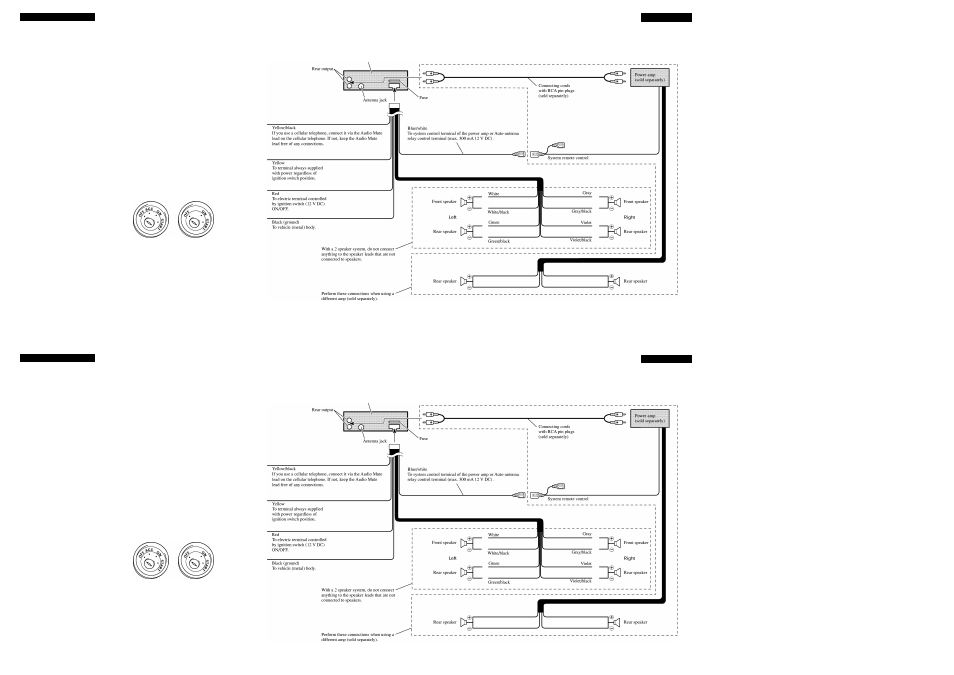
When this product’s source is switched ON, a
control signal is output through the blue/white
lead. Connect to an external power amp’s system
remote control or the car’s Auto-antenna relay
control terminal (max. 300 mA 12 V DC). If the
car features a glass antenna, connect to the anten
na booster power supply terminal.
When an external power amp is being used with
this system, be sure not to connect the blue/white
lead to the amp’s power terminal. Likewise, do
not connect the blue/white lead to the power ter
minal of the auto-antenna. Such connection could
cause excessive current drain and malfunction.
To avoid short-circuiting, cover the disconnected
lead with insulating tape. Especially, insulate the
unused speaker leads without fail. There is a pos
sibility of short-circuiting if the leads are not insu
lated.
If this unit is installed in a vehicle that does not
have an ACC (accessory) position on the ignition
switch, the red lead of the unit should be connect
ed to a terminal coupled with ignition switch
ON/OFF operations. If this is not done, the vehi
cle battery may be drained when you are away
from the vehicle for several hours. (Fig. 4)
ACC position
No ACC position
Fig. 4
Cords l'or lilis produci and ihose foj- oilier prod
ucís ma> be din'erenl colors e\en if llie> lia\e die
same ruiiclion. W lieu connecling ibis proilucl lo
aiiolher produci, rerer lo die supplied liisiallalioii
manuals of bolli products and conned cords tlial
ha\e die same lunclion.
This product
Fig. 5
Connecting the Units
<ENGLISH>
Note:
•
This unit is for vehicles with a 12-volt battery and
negative grounding. Before installing it in a recre
ational vehicle, truck, or bus, check the battery
voltage.
•
To avoid shorts in the electrical system, be sure to
disconnect the © battery cable before beginning
installation.
•
Refer to the owner’s manual for details on con
necting the power amp and other units, then make
connections correctly.
•
Secure the wiring with cable clamps or adhesive
tape. To protect the wiring, wrap adhesive tape
around them where they lie against metal parts.
•
Route and secure all wiring so it cannot touch any
moving parts, such as the gear shift, handbrake
and seat rails. Do not route wiring in places that
get hot, such as near the heater outlet. If the insu
lation of the wiring melts or gets tom, there is a
danger of the wiring short-circuiting to the vehicle
body.
•
Don’t pass the yellow lead through a hole into the
engine compartment to connect to the battery.
This will damage the lead insulation and cause a
very dangerous short.
•
Do not shorten any leads. If you do, the protection
circuit may fail to work when it should.
•
Never feed power to other equipment by cutting
the insulation of the power supply lead of the unit
and tapping into the lead. The current capacity of
the lead will be exceeded, causing overheating.
•
"When replacing fuse, be sure to use only fuse of
the rating prescribed on this unit.
•
Since a unique BPTL circuit is employed, never
wire so the speaker leads are directly grounded or
the left and right © speaker leads are common.
•
The black lead is ground. Please ground this lead
separately from the ground of high-current prod
ucts such as power amps.
If you ground the products together and the
ground becomes detached, there is a risk of dam
age to the products or fire.
Speakers connected to this unit must be high-
power types with minimum rating of 45 "W and
impedance of 4 to 8 ohms. Connecting speakers
with output and/or impedance values other than
those noted here may result in the speakers catch
ing fire, emitting smoke or becoming damaged.
"When this product’s source is switched ON, a
control signal is output through the blue/white
lead. Connect to an external power amp’s system
remote control or the car’s Auto-antenna relay
control terminal (max. 300 mA 12 'V DC). If the
car features a glass antenna, connect to the anten
na booster power supply terminal.
"When an external power amp is being used with
this system, be sure not to connect the blue/white
lead to the amp’s power terminal. Likewise, do
not connect the blue/white lead to the power ter
minal of the auto-antenna. Such connection could
cause excessive current drain and malfunction.
To avoid short-circuiting, cover the disconnected
lead with insulating tape. Especially, insulate the
unused speaker leads without fail. There is a pos
sibility of short-circuiting if the leads are not insu
lated.
If this unit is installed in a vehicle that does not
have an ACC (accessory) position on the ignition
switch, the red lead of the unit should be connect
ed to a terminal coupled with ignition switch
ON/OFF operations. If this is not done, the vehi
cle battery may be drained when you are away
from the vehicle for several hours. (Fig. 4)
ACC position
No ACC position
Fig. 4
Cords l'or lilis produci and ihose for oilier prod
ucís ma> be diri'erenl colors e\eii if llie> lia\e die
same ruiiclion. W lieu coiinecling lliis proilucl lo
aiiolher produci, rel'er lo die supplied liisiallalioii
manuals of bolli products and conned cords tlial
ha\e die same lunclion.
This product
Fig. 5