Wire description, Ems 1.9r, Настройка датчиков – Инструкция по эксплуатации Mongoose EMS 1.9R
Страница 5
Two Way Car Alarm System MONGOOSE EMS 1.9R
5
ENGLISH
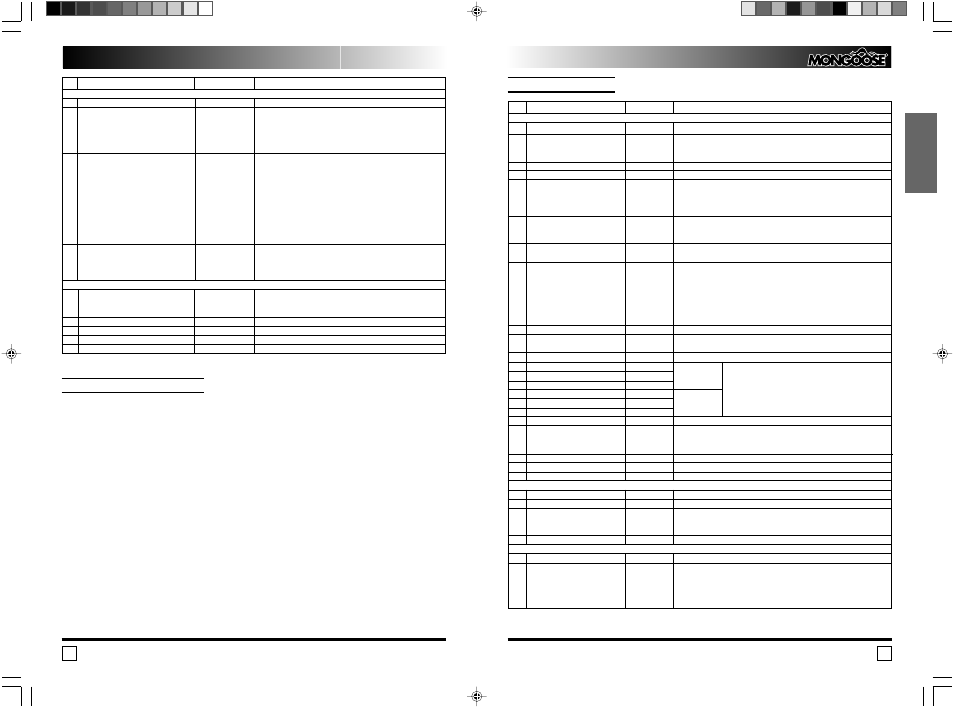
Wire Description
1
Not Used
2
Positive Programmable Input
The mode of the input operation
is set by the Installer function 1 6.
3
Handbrake Input ( )
4
Negative Door Trigger Input
5
Negative Trunk Trigger Input
6
Negative Hood Trigger input
7
Ignition 2 Output “ ” 300mA
8
Negative Central Door Lock Control Input
One of two options can be selected
for this input with the Installer
Function 2 6.
1. CDL Control Input.
2. CDL Control Input with arming on
locking.
9
Ground “ ”
10
Remote Starter Control Input
11
Main Unit Power Supply
12
Lock Normally Closed Contact
13
Lock Common Contact
14
Lock Normally Opened Contact
15
Unlock Normally Closed Contact
16
Unlock Common Contact
17
Unlock Normally Opened Contact
18
Indicators Output 1
19
Indicators Polarity
20
Indicators Output 2
21
Not Used
22
Siren Output
1
Remote Start System Power Supply
2
Starter Output +12V
3
ACC Output +12V
The installer`s function 3 1 set the
delay of activation the output.
4
Ignition +12V
1
Trunk Release Output “ ” 300 mA
2
Comfort/2 Stage unlock Output
“ ” 300 mA
Yellow
Blue/White
Green
Grey
Grey/White
Blue/Black
Brown/Black
Black
Purple
Red
Grey/Yellow
Grey/Red
Red/Yellow
Blue/Yellow
Blue/Red
Red/Black
Black/Green
Red
Black/White
Brown
Red
Black/Yellow
Blue
Black
Blue/Black
Green/White
N
Wire Destination
Wire Color
Note
18 pin Connector
1. Positive Door Trigger Input.
2. Shining Light Warning. (Connect to the Parking Lights Feed Wire).
Connect to the handbrake switch.
The input has the “Dome Light Cars” selectable option. (Installer function 1 7).
While remote trunk opening in armed stage the input will be overridden until 10
seconds of trunk is closed. The trunk pin switch should be mounted onto the car
body metal. Make sure the switch is reliable disconnected when the trunk cowl is
closed, and will be grounded as soon as the trunk is opened.
The hood pin switch should be mounted onto the car body metal. Make sure the
switch is reliable disconnected when the hood is closed, and will be grounded as
soon as the hood is opened.
Connect to the coil of external relay to feed the ignition 2 line (if exists).
The output can also be used to by pass a OE Immobiliser while remote starting.
Connect to the master actuator output, which is grounded in “open” position and
stays free in “closed” position.
Connect to the car body.
Depend on the setting of the Installer`s function 2 5 connect to either the RPM
line or Generator or Oil Lamp.
Connect to +12V contact of the car battery via 5A fuse.
Built in Relay
See Central Door Lock Connection Diagrams
Built in Relay
Built in Relay Contact. Connect to the right side indicators feed wire.
Connect to +12V contact of the car battery via 15A fuse.
(In case of negative polarity of the Indicator control wire connect to the car body
via 15A fuse).
Built in Relay Contact. Connect to the left side indicators feed wire.
+ 2A
Connect to +12V contact of the car battery via 30A fuse.
Connect to the starter relay control line.
Connect to the ACC wire at the ignition key cylinder.
Depending on program setting the output can be switched on in either 1 minute
or 2 seconds after the engine is started up.
Connect to the Ignition wire at the ignition key cylinder.
Connect to the coil of the trunk release relay.
You can select one of two options for the output with Installer’s function 3 1:
1. 20 secon Comfort Window Close on Arming.
(Connect to the coil of the
window closing relay).
2. Two stage Unlock.
(Connect to the coil of passengers’ door unlocking
relay).
Power 4 pin Connector of the Remote Start System
4 pin Low Current Connector (Red Color)
Инструкция по установке
EMS 1.9R
16
4
Выход зажигания +12 В
Черный
Подключить проводу Зажигание в разъеме ключа зажигания.
4 контактный разъем слаботочных выходов (красного цвета)
1
Выход отпирания багажника “ ”300 мА
Голубой/черный
Подключить к обмотке внешнего реле управления замком багажника.
2
Программируемый выход 1 “ ”300 мА
Зеленый/белый
1. 20 секундный импульс при постановке на охрану.
Режим работы выхода задается
(Подключить обмотке реле управления поднятием стекол).
функцией 3 1 в Таблице установочных
2. Двушаговое отпирание дверей при снятии с охраны и
функций
включенном зажигании.
(Подключить к обмотке реле отпирания пассажирских дверей).
3
Программируемый выход 2 “ ”300 мА
Белый
1. Импульс с фиксацией.
Режим работы выхода задается
Канал активизируется 3 х секундным нажатием кнопки 2
функцией 1 8 в Таблице установочных
независимо от положения ключа зажигания и режима, в
функций
котором находится охранная система. При снятии с охраны или
повторном 3 х секундном нажатии кнопки 2 выход отключается.
2. Выход тормозных фонарей.
Для автомобилей где включение стартера разрешается только
при нажатой педали тормоза.
Подключить к обмотке
дополнительного реле для подачи +12В в цепь питания
тормозных фонарей.
4
Выход состояния (программируемый).
Коричневый/белый
1. “ ”300 мА при включенной охране.
Режим работы выхода задается
Для управления нормально замкнутым реле блокировки.
функцией 1 4 в таблице установочных
2. “ ”300 мА при отключенной охране.
функций.
Для управления нормально разомкнутым реле блокировки.
Прочие подключения
Силовой выход блокировки двигателя
Два черных провода
Внутреннее реле. Провода выведены через отверстие
с разъемом
центрального блока управления.
(Подключить в разрыв блокируемой цепи)
Выход светодиода
2 контактный разъем белого цвета
Вход кнопки аварийного отключения
2 контактный разъем белого цвета
Два входа двухуровневых датчиков
Два 4 контактных разъема белого цвета
Вход модуля связи
4 контактный разъем черного цвета
Настройка датчиков.
При настройке датчика удара и, если установлен, дополнительного датчика устано
вите регуляторы чувствительности в среднее положение. Проверьте чувствительность
датчика удара, постукивая рукой по кузову автомобиля. Чувствительность объемного
датчика проверяется движением руки в салоне через приоткрытое окно для однозонного
датчика или основной зоны двузонного датчика; чувствительность предупредительной
зоны проверяется движением вблизи автомобиля.
При необходимости увеличить чувствительность датчика поверните регулятор по
часовой стрелке, для уменьшения чувствительности – против часовой стрелки.
Помните, что избыточная чувствительность может привести к большому числу лож
ных срабатываний системы.