Wiring description, Moдель: tt2, Схемы подключения к центральному замку – Инструкция по эксплуатации Mongoose TT2
Страница 7
Car Alarm System MONGOOSE TT2.
3
ENGLISH
Wiring Description
Main 20-pin Connector
1
Siren Output
Brown
2
Pager Output
White
3
Arm Output (programmable).
Brown/White
The mode operation of the Arm
Output you select with Installer’s
function 1-5.
4
Negative Trunk Trigger Input
Grey
5
Trunk Release Output “-” 300 mA
Blue/Black
6
Ignition Input
Orange
7
Negative Door Trigger Input
Green
8
Negative Central Door Lock
Brown/Black
Control Input
One of two options can be
selected for this input with the
Installer Function 1-1.
1. CDL Control Input.
2. CDL Control Input with arming
on locking.
9
Ground “-”
Black
10
Main Unit Power Supply
Green/Brown
11
Lock Normally Closed Contact
Grey/Yellow
12
Lock Common Contact
Grey/Red
13
Lock Normally Opened Contact
Red/Yellow
14
Unlock Normally Closed Contact
Blue/Yellow
15
Unlock Common Contact
Blue/Red
16
Unlock Normally Opened Contact
Red/Black
17
Positive Programmable Input
Yellow
The mode of the input operation is
set by the Installer function 1-6.
18
Indicators Output
Black/Green
19
Indicators Polarity
Red
20
Indicators Output
Black/White
External Components Sockets
LED Output
2-pin White Connector
Override Switch Input
2-pin White Connector
Shock Senor and Optional Sensor
Two 4-pin White Connectors
Inputs
Side Exited Wires
Ignition Support/Turbo Timer Output Brown/Black
Connect to an extra relay to feed power to the ignition line while arming with
“-”300 mA
engine running and switching on the turbo timer mode.
The duration of pulse depends upon the remote control command.
Comfort Output/Two-Stage unlock
Green/Red Wire Two possible options:
Output “-”300 mA
1. 20-secon Comfort Window Close on Arming. (Connect to the coil of the
The mode of the input operation is
window-closing relay).
set by the Installer function 2-1.
2. Two-Stage Unlock on disarming and with the ignition turned on (Connect
to the coil of passenger’s doors unlock relay).
Power Immobiliser Relay
Two Side Exited Built-in normally closed relay.
Orange Wires
with connector
N
Wire Destination
Wire Color
Note
+ 2 A
Connect “+” wire of the pager.
1. “-”300 mA when Armed.
To control an extra normally closed blocking relay.
2. “-”300 mA when Disarmed.
To control an extra normally opened blocking
relay.
While remote trunk opening in armed stage the input will be overridden until 10
seconds of trunk is closed.
The trunk pin switch should be mounted onto the car body metal. Make sure the
switch is reliable disconnected when the trunk cowl is closed, and will be grounded
as soon as the trunk is opened.
Connect to the coil of the trunk release relay.
Connect the Ignition line, where +12V appears at switching the ignition on and
stays while cranking.
The input has the “Dome Light Cars” selectable option.
(Installer function 1-7).
Connect to the master-actuator output, which is grounded in “open” position and
stays free in “closed” position.
Connect to the car body.
Connect to +12V contact of the car battery via 15A fuse.
Built-in Relay
See Central Door Lock Connection Diagrams
Built-in Relay
1. Positive Door Trigger Input.
2. Shining Light Warning.
(Connect to the Parking Lights Feed Wire).
Built-in Relay Contact.
Connect to the right side indicators feed wire.
Connect to +12V contact of the car battery via 15A fuse.
(In case of negative polarity of the Indicator control wire connect to the car body
via 15A fuse).
Built-in Relay Contact.
Connect to the left side indicators feed wire.
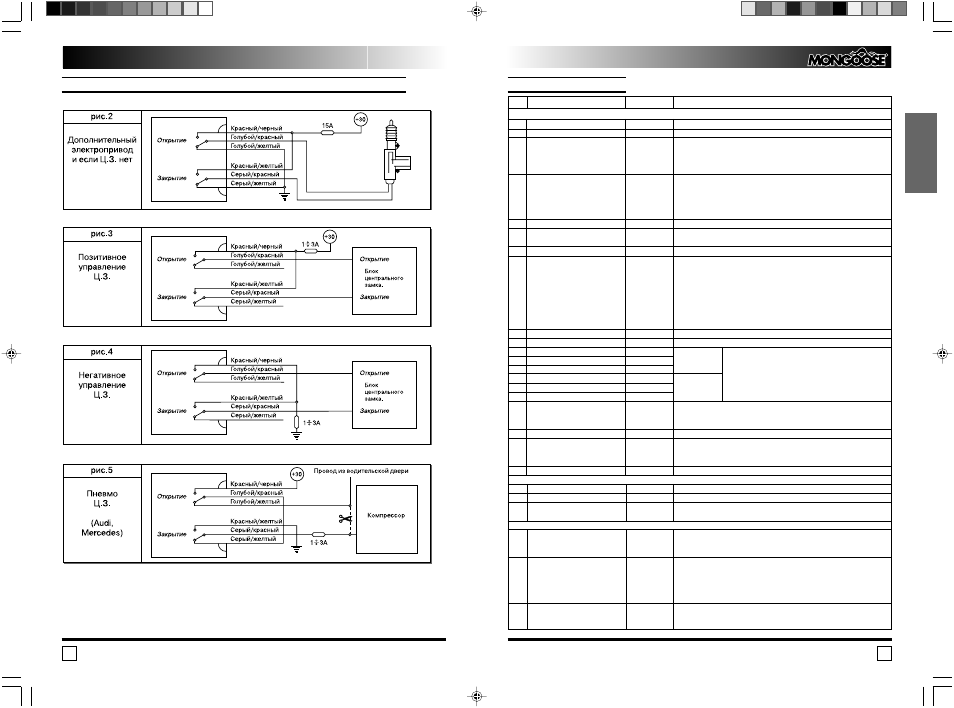
Инструкция по установке.
Moдель: TT2
14
СХЕМЫ ПОДКЛЮЧЕНИЯ К ЦЕНТРАЛЬНОМУ ЗАМКУ