Single-hole washbasin mixer – Инструкция по эксплуатации Graff SINGLE-HOLE WASHBASIN MIXER
Страница 4
IOG 2386.00
Rev. 2 August 2010
4
GB D
F RUS E
IT
WASCHBECKENBATTERIEN MIT 1 ÖFFNUNG • ROBINETTERIES DE LAVABO 1 TROU
СМЕСИТЕЛЬ ДЛЯ УМЫВАЛЬНИКА С 1 ОТВЕРСТИЕМ
GRIFOS LAVABO DE 1 HUECO • BATTERIE LAVABO MONOFORE
Instructions for assembly and use • Montage- und Gebrauchsanweisung • Notice technique montage et utilisation • Инcтрукция по монтажу и обслуживанию • Instrucción de Montaje y Servicio • Manuale di Montaggio e Uso
SINGLE-HOLE WASHBASIN MIXER
1
2
16
17
14
18
19
G3/8"
G3/8"
20
13
12
11
MAX. 45mm
Ø32mm
16
17
18
19
20
21
22
A
B
C
Base washer
Rubber washer
Metal washer
Mounting nut
Supply hose M8x1 GZ -
G3/8" GW, length 400mm
(2 pcs.)
Female/male union G1/2”-
G3/8” (2 pcs.)
Washer (2 pcs.)
2.5mm hex key
1.5mm hex key
Special key for the aerator
MT – male thread
FT – female thread
Sockelunterlegscheibe
Gummischeibe
Metallscheibe
Montagemutter
Speiseschlauch M8x1 GZ -
G3/8” GW, Länge 400mm
(2 Stück)
Aufschraub-Einschraubmuffe G1/2” -
G3/8” (2 Stück)
Flachdichtung (2 Stück)
Innensechskantschlüssel 2,5mm
Innensechskantschlüssel 1,5mm
Spezialschlüssel für Luftsprudler
AG – Außengewinde
IG – Innengewinde
Rondelle du support
Rondelle caoutchouc
Rondelle métallique
Ecrou de fixation
Flexible d'alimentation M8x1 FE -
G3/8” FI, d'une longueur de
400mm (2 pièces)
Raccord mâle-femelle G1/2”-G3/8”
(2 pièces)
Joint plat (2 pièces)
Clé Allen 2,5mm
Clé Allen 1,5mm
Clé spéciale pour brise-jet
FE – filetage extérieur
FI – filetage intérieur
Шайба гильзы
Резиновая шайба
Металлическая шайба
Монтажная гайка
Шланг подачи воды M8x1 GZ -
G3/8” GW, длина 400мм (2 шт.)
Футорка G1/2” - G3/8” (2 шт.)
Плоская прокладка (2 шт.)
Имбусный ключик 2,5мм
Имбусный ключик 1,5мм
Специальный ключ для перлатора
GZ – наружная резьба
GW – внутренняя резьба
Arandela de la base
Arandela de caucho
Arandela de metal
Tuerca de montaje
Manguera de suministro,
M8x1 GZ-G3/8" GW, longitud de
400mm (2 piezas)
Niple G1/2”-G3/8” (2 unid.)
Junta plana (2 unid.)
Llave allen 2,5mm
Llave allen 1,5mm
Llave especial para el aereador
RE – rosca externa
RI – rosca interna
Rondella dello zoccolo
Rondella di gomma
Rondella di metallo
Dado di montaggio
Flessibile di alimentazione
M8x1 FE - G3/8” FI, lunghezza
400mm (2 pezzi)
Raccordo filettato G1/2” - G3/8”
(2 pezzi)
Guarnizione piatta (2 pezzi)
Chiave a brugola 2,5mm
Chiave a brugola 1,5mm
Chiave speciale per aeratore
FE – filetto esterno
FI – filetto interno
2
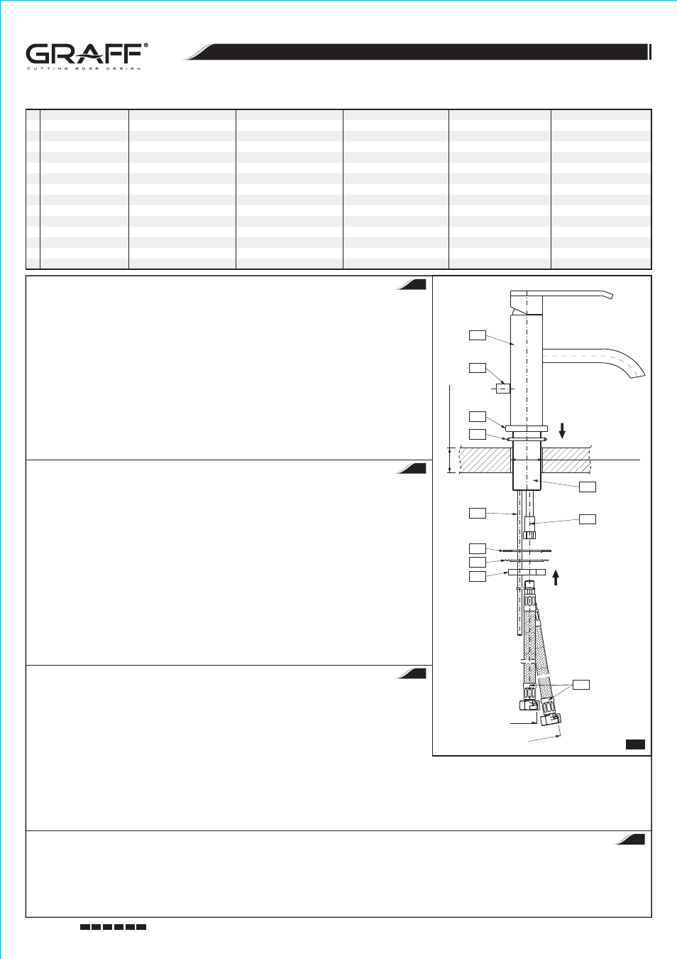
MIXER INSTALLATION - see fig. 2
1. Hand tighten the supply hoses
(20) into the threaded ends of copper lines (12). (With the spout facing towards you, screw the red labeled
hose into the left tube and the blue labeled hose into the right tube).
2.
Note: In QUBIC 2386000 (PC), 2386100 (PC) and QUBIC TRE 2389100 (PC), 2389200 (PC) models: Slide the lift rod (14) under the
mixer into the hole in the setting insert
(15). Next, screw the lift rod (14) into the knob (13) and position the knob properly in the notch on
the back of the mixer's body
(1).
3.
Insert the rubber washer
(16) into the undercut of the mixer base (2). Make sure that the washer stays flat inside the undercut.
4.
Insert both supply hoses
(20), the lift rod (14), and the threaded stub pipe (11) through the hole of designated install.
5.
Slide the rubber washer
(17) under the designated hole, with the metal washer (18) underneath it, on the threaded stub pipe (11).
6.
Screw the mounting nut
(19) hand tighten to the top of the threaded stub pipe (11). Adjust the spout to be in the right position, then tighten
the mounting nut
(19) with an adjustable wrench.
For information on how to install the drain system in QUBIC 2386000 (PC), 2386100 (PC) and QUBIC TRE 2389100 (PC), 2389200 (PC)
models, see page 5.
For information on how to install the automatic drain system in QUBIC 2386200 (PC), 2386300 (PC), 2386400 (PC) and QUBIC TRE
2389300 (PC), 2389400 (PC), 2389500 (PC) models, see page 6.
MONTAGE DER BATTERIE - siehe Abb. 2
1.
Die Speiseschläuche
(20) in die Gewindeenden der Kupferrohre (12) eindrehen. Den Schlauch mit roter Markierung in das linke Rohr
und den mit der blauen Markierung in das rechte Rohr eindrehen, unter Voraussetzung, dass die Auslaufgarnitur der Batterie auf den
Benutzer zeigt.
2.
Anmerkung: Für die Modelle QUBIC 2386000 (PC), 2386100 (PC) und QUBIC TRE 2389100 (PC), 2389200 (PC) ist von der
Batterieunterseite in die Öffnung in der Feststellscheibe
(15) die Zugstange (14) einzuschieben, dann die Zugstange (14) in den
Drehknopf
(13) einzudrehen, die richtig in der Rille hinten am Batteriekörper (1) zu positionieren ist.
3.
Die Gummischeibe
(16) in die Rille im Batteriesockel (2) einlegen. Vergewissern Sie sich, dass die Scheibe richtig in der Rille
positioniert ist.
4.
Die beiden Speiseschläuche
(20), die Zugstange (14) und den Gewindestutzen (11) durch den Batteriesockel (10) umlegen.
5.
Die Gummischeibe
(17) und Metallscheibe (18) auf den Gewindestutzen (11) von unten der Montagefläche aufschieben.
6.
Die Montagemutter
(19) auf den Gewindestutzen (11) aufschrauben. Die Batterie auf der Montagefläche richtig positionieren und die
Montagemutter
(19) mit dem Stellschlüssel festziehen.
Für die Modelle QUBIC 2386000 (PC), 2386100 (PC) und QUBIC TRE 2389100 (PC), 2389200 (PC) Beschreibung des Ablasssatzes –
siehe Seite 5.
Für die Modelle QUBIC 2386200 (PC), 2386300 (PC), 2386400 (PC) und QUBIC TRE 2389300 (PC), 2389400 (PC), 2389500 (PC)
Beschreibung des Automatik-Ablasssatzes – siehe Seite 6.
MONTAGE DE LA ROBINETTERIE - voir schéma 2
1. Vissez les flexibles d'alimentation
(20) dans les embouts filetés des tuyaux en cuivre (12). Vissez le flexible marqué par l'étiquette rouge
sur le tuyau situé à gauche et celui marqué par l'étiquette bleu sur le tuyau situé à droite, le robinet étant dirigé vers l'Utilisateur.
2.
Attention : pour les modèles QUBIC 2386000 (PC), 2386100 (PC) et QUBIC TRE 2389100 (PC), 2389200 (PC) faites coulisser la tige
de commande
(14) par le dessous de la robinetterie dans le perçage de la semelle de fixation (15), puis vissez la tige (14) dans le
poussoir de commande
(13) qui doit être positionné correctement dans la rainure située à l'arrière du corps de robinetterie (1).
3. Mettez la rondelle caoutchouc
(16) dans la rainure du support de robinetterie (2). Assurez-vous que la rondelle est positionnée
correctement dans la rainure.
МОНТАЖ СМЕСИТЕЛЯ - см. рис. 2
1.
Ввинти шланги подачи воды
(20) в наконечники медных трубок с резьбой (12). Шланг, обозначенный красной этикеткой, ввинти в трубки с левой стороны, а обозначенный синей этикеткой - в трубки с
правой стороны, принимая, что смеситель направлен изливом в сторону Пользователя.
2.
Внимание: Для моделей QUBIC 2386000 (PC), 2386100 (PC) и QUBIC TRE 2389100 (PC), 2389200 (PC) задвинь снизу смесителя стержень шатуна (14) в отверстие в установочном вкладыше (15), затем
ввинти стержень
(14) в головку шатуна (13), которую надо установить в правильном положении в бороздке в корпусе смесителя (1).
3.
Вложи резиновую шайбу
(16) в бороздку в гильзе смесителя (2). Убедись, что шайба правильно уложена в бороздке.
4. Faites passer les deux flexibles d'alimentation
(20), la tige de commande (14) et l'embout fileté (11) par le perçage de montage.
5. Par le dessous de la surface de montage placez la rondelle caoutchouc
(17) et la rondelle métallique (18) sur l'embout fileté (11).
6. Vissez l'écrou de fixation
(19) sur l'embout fileté (11). Positionnez correctement la robinetterie sur la surface de montage et serrez l'écrou de fixation (19) à l'aide de la clй а molette.
Pour les modèles QUBIC 2386000 (PC), 2386100 (PC) et QUBIC TRE 2389100 (PC), 2389200 (PC) description du montage de l'ensemble de vidange - voir page 5.
Pour les modèles QUBIC 2386200 (PC), 2386300 (PC), 2386400 (PC) et QUBIC TRE 2389300 (PC), 2389400 (PC), 2389500 (PC) description du montage de l'ensemble de vidange automatique - voir page 6.
GB
D
F
RUS