Unit description operating instructions – Инструкция по эксплуатации Elenberg FS-4006
Страница 9
9
pipe and slide pipe connector over upper pipe onto lower pipe and
tighten.
4. Attach the motor with switch compartment onto the upper pipe. Ensure
the switch compartment is pushed fully onto the upper pipe and se-
cured with the screw provided.
5. Loosen Guard Mounting Nut from the Motor Housing.
6. Position rear guard firmly to motor housing and then fasten by turning
guard mounting nut clockwise tightly.
7. Push the blade along motor shaft, fasten it firmly with spinner by turn-
ing counter clockwise.
8. Hang the Front Guard to Rear Guard with the position fixer provided
at the rim of Guard, and then fix together with clips provided. Pay at-
tention that the hole for the metric at the rim from the front and back
guard are in line. Insert the screw through the holes and screw on the
nut.
OSCILLATION CONTROL
1. Push the oscillation knob to oscillate.
2. Pull the oscillation knob to stop.
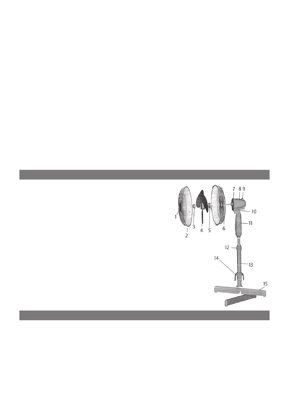
1. GUARD ORNAMENT
2. FRONT GUARD
3. SPINNER
4. FAN BLADE
5. GUARD MOUNTING NUT
6. REAR GUARD
7. FRONT MOTOR COVER
8. REAR MOTOR COVER
9. OSCILLATION KNOB
10. NECK PIECE ASSEMBLY
11. SWITCH COMPARTMENT
12. HEIGHT ADJUSTER
13. LOWER METAL PIPE
14. BASE ORNAMENT
15. X-BASE
1. Plug the power cord into a suitable socket.
2. To engage/dis-engage the head oscillation, push in/pull out the clutch
knob.
3. Tilt the head up or down to the required position. There is a click mech-
anism that will hold the head in the desired position.
4. The fan is switched on using the push buttons on the base, i.e.
0: Off, 1 = Low Speed, 2 = Medium Speed, 3 = Maximum speed
UNIT DESCRIPTION
OPERATING INSTRUCTIONS